When you click on links to various merchants on this site and make a purchase, this can result in this site earning a commission. Affiliate programs and affiliations include, but are not limited to, the eBay Partner Network.
If that front fitting is used for the "dirty" or "foul"side, then it is different from the N14 that has the dirty outlet on the rear passenger side. The diagram you show appears to be the cleanside allowing air into the crankcase itself. So, can you clarify the N18 has not opening that runs directly to the intake manifold from the passenger side rear of the valve cover? The N14 has the checkvalve in that rear opening.
All PCV systems must have a clean or fresh side, and a foul or dirty side like the N14 in the videos and pictures I posted. That would be the only engine we have not inspected in detail.
One of the reasons the mini is so prone to severe intake valve coking is the poor design. The larger BMW's have a very robust PCv system on those turbo applications.
Great pic showing the N18 has the flapper type valve in the front opening. Just need to see the rest.
From what I can guess the above picture is some type of heavy knock out ( heavy oil,liquid oil etc) has a chance to drain back into the motor. This is still hot oil so your not going to get the milk-water-nasty stuff like you catch in your catch cans.
Who knows, wish there was a good fix , RX looks nice tho
Excellent! With that flowing out only, it is then the dirty side and the other tube entering the crankcase in the rear would be the clean side. Can you verify flow on the other tube? Thanks, this is what we need.
Excellent! With that flowing out only, it is then the dirty side and the other tube entering the crankcase in the rear would be the clean side. Can you verify flow on the other tube? Thanks, this is what we need.
Both are "dirty" and that's just how it is. The fact is that most of the time there is vacuum on the crankcase. For the times there is a bit of pressure from blowby, high boost, etc, it is sucked out the back of the intake manifold after the throttle body if pulling vacuum, and it gets sucked out the driver's side port if the greater source of vacuum is the inlet tube after the MAF.
There's always vacuum. If boosting, the rear is closed off and then the inlet tube has more vacuum and vapors go there. If not on boost, then it goes out the rear passenger port. Problem is that most of the time you will drive around off boost, so it's going to favor the rear exit. If the pcv is the older style or not functioning correctly, a lot will go out the back.
If it's functioning correctly, I think a dual catch can with 1 on each port would be optimal so everything isn't drawn through the rear diaphragm that probably isn't meant to ALWAYS be loading with oil. Leave the PCV to function as normal, but add catch cans in-line and I would probably also put check valves in them just to have more to rely on than the built in pcv flaps and holes stopping boosted air/oil.
Try this if you would. At idle, if the front is the dirty side, then you will feel strong suction on the rear as it brings in replacement air. It appears where the N14 uses intake manifold vacuum on the rear fitting, and the front is fresh incoming air that the N18 uses the rear.
Not to argue, but I am an automotive engineer that designs PCV systems and have for nearly 4 decades. Many do it differently (and I have not worked for BMW), but all have a dirty and a clean side. It is just if they use intake manifold vacuum for evacuation or they use turbo inlet suction (GM 2.0T L4 engine only uses turbo inlet, Ford ecoboost only uses intake manifold vacuum). The newer inline 6 BMW twin turbo uses both with solenoids for switching and that is the most robust we have seen to date.
Under stand the dual valve ALWAYS pulls suction so there is never pressure allowed to build in the crankcase similar to a belt driven vacuum pump. The goal here is twofold. First, stop the oil and other contaminates from ingestion that causes the intake valve coking and other wear associated with them. Second is the improvement of the PCV systems function. This is by simply designating a separate clean and dirty side so always clean, fresh filtered air (if MAF equipped then MAF metered) entering one portion of the crankcase to flush and replace the foul oil and contaminant vapors being evacuated out the opposite portion. And by utilizing the 2 separate evacuation suction sources, you maintain suction at all times, boost or non-boost as the check valves always select the strongest source to evacuate. This not only solves the coking issue, but eliminates the added detonation and KR due to knock sensors giving data to the ECU that then pulls timing to halt the detonation, but it also keeps the engine oil far cleaner and contaminant free (where the way it works as it comes stock is allowing excessive abrasive contaminants to enter and accumulate in the oil as well as the oil ingestion. Then we have the elimination of the parasitic power loss fighting crankcase pressure. This and the added stability to the piston rings preventing crankcase pressure improves piston/ring/cylinder seal reducing blow-by. There is no negative to do this correctly, and more and more automakers are short cutting on this. By utilizing a dual valve system, you take GM's and Ford's suction sources and combine them to greatly improve all of this.
To date, all I have seen is adding cans inline and not addressing the root cause of what is causing these issues. So it takes stepping back from how the factory does this, and studying what would improve and correct the issues. So that is where (unless I can get a N18 in to the shop to study...anyone in FL with one I would do the installation free so it can be documented and any custom fittings machined) this approach comes in.
So I greatly appreciated when you guy's help providing pics, etc. and discussing this. This helps all and until I can get a car in here personally to study, I need your help.
Question- this "clean" air thats metered air (through the MAF) , Is there a MAF that monitors the "clean" air thats being "sucked" into the valve cover to "flush and replace the foul oil" have a MAF of its own ? If your robbing the air that has already been metered then the ECU needs to know how much air you are robbing in order to know how much fuel or timing the motor needs ?????
I'm still confused on how you can still say air goes into the valve cover , but most salesmen I deal with at work are the same way, they just keep digging and digging to try to get us to use their products...... I'm not saying your can is a bad one, I'm just saying your thought process on the system seams to have a lot of blow by........
Both are "dirty" and that's just how it is. The fact is that most of the time there is vacuum on the crankcase. For the times there is a bit of pressure from blowby, high boost, etc, it is sucked out the back of the intake manifold after the throttle body if pulling vacuum, and it gets sucked out the driver's side port if the greater source of vacuum is the inlet tube after the MAF.
There's always vacuum. If boosting, the rear is closed off and then the inlet tube has more vacuum and vapors go there. If not on boost, then it goes out the rear passenger port. Problem is that most of the time you will drive around off boost, so it's going to favor the rear exit. If the pcv is the older style or not functioning correctly, a lot will go out the back.
If it's functioning correctly, I think a dual catch can with 1 on each port would be optimal so everything isn't drawn through the rear diaphragm that probably isn't meant to ALWAYS be loading with oil. Leave the PCV to function as normal, but add catch cans in-line and I would probably also put check valves in them just to have more to rely on than the built in pcv flaps and holes stopping boosted air/oil.
Yeah, totally agree based on my studies of my n14 CC system.
Both sides are dirty and when pass shuts down, the drivers vents the gases directly into the intlet of the turbo; that el suck-o-'s to say the least.
There is slight vacuum when under idle and very light throttle b/c the pass. side is open and receiving vacuum.
Further the crankcase needs no source of air (its nice to have in theory and I did it) but its superfluous as the crank creates both pressure and, alternatively is exposed to vacuum. My setup is so simple and effective and race proven on the track; Sonoma raceway. My only issue is long term fuel trims. They get a little lean after many days.
Along this issue I see taking metered air (down stream from MAS) and rerouting it to the crank as defeatus. Why??? To provide air to the crank so that it funnels back into the inlet of the turbo all fouled (despite the best efforts of the OCC).
I understand the concept, I guess it works but.......since I created mine and I'm insecure and.....hahaa lol.
Whatever works; fun to tinker and see different solutions.
BTW, my system will outlet to atmosphere if pressure ever builds over 2-3psi in the crank. I use several 1 way valves and pressure sensitive release valves when high reving for prolonged periods of time.
All moot now as my engine is blown up...not related
Just wanted to thank you all your help. The system you created and recommended works perfectly! No oil residues around the rocker cover, oil consumption is also minimized and there is no 'smell' as such. :-)
Trying to share info for others here to understand all that is involved in proper crankcase evacuation, especially when it is a turbo or centri blower application but this is proving pretty difficult. Will still work on it as once it "clicks" then it seems so simple. But with so much misunderstanding and mis-information it is easier said than done!
The N14 design is down and proven, but still need to get a N18 in here to determine just where the rear tube runs on both ends and to test the flow before I have that down.
Tracy, Just wanted to thank you all your help. The system you created and recommended works perfectly! No oil residues around the rocker cover, oil consumption is also minimized and there is no 'smell' as such. :-) Cheers
How can oil consumption be minimized? Maybe I don't understand the process all that well.
Oil consumption has several possible points of ingestion, one is the piston rings and that is dependent on how well the rings seated during the initial break-in, and 90% happens in the first 50100 miles, and the rest by 400 or so. After this point the brief window will have past as the cylinder walls form a hard glaze on them and the rings can no longer be abraded into the shape of the cylinder walls, even though the cross hatch is still visible. If the rings are not loaded equally from both acceleration and engine breaking deceleration at a rate that can over come the lubrication barrier, then a partial, or incomplete seating is the result and excessive blow-by will always result in oil consumption unless torn down, glaze cut with a re-hone, new rings and start over. Then we have the most common, and they are the piston rings become "gummed up" from oil entering via the intake air charge, from the PCV system as it enters the intake tract. This will gradually build of residue/varnish/carbon in the ringlands and on the rings themselves causing them to stick and not move freely as needed to seal properly. Once you modify the system to separate and trap the oil and other compounds that form this varnish, the rings will generally free up as the varnish/deposits wear and the rings can once again do their job properly. If this ingestion is not stopped (and it is more than just the oil mist you see when you remove the turbo inlet tube and inspect it as well as the intake manifold) this build-up is constantly growing as more adheres. So, as long as the rings have properly seated in the beginning (best is when new, drain factory oil fill...replace with a good conventional oil and after several heat cycles to ensure no leaks or issues, in second gear from a roll full throttle to 5k or so and then allow engine braking back down. Do this 3-5 times and rings are seated properly and odds are will never be better. Then drain oil and fill w/full synthetic (filter change also).
On cars with over 20k miles that have oil consumption stopping the ingestion usually will result in no oil usage after 500-1000 miles of running to clean it out. We see this in just over 50% of oil burners (in newer vehicles). The rest have some improvement.
What most do not realize is as the Mini comes from the factory, and how most "catchcans" are installed, the flawed design of the PCV system is left as is almost always retaining pressure in the crankcase instead of evacuating and pulling suction, so this results in a less stable piston ring during operation, especially at higher RPM's (ring flutter). This also results in greater oil entering the combustion chamber as well greater blow-by. All resulting in oil usage and less power. You always want vacuum/suction pulled on the crankcase, especially with FI. That is what I have been posting about all along, and leaving the PCV as is, or doing the many mods that defeat or delete compound this issue. Done correctly as the dual valve does, you never have pressure, you always have good evacuation flow at all times, and fresh flushing air entering at a controlled rate. No downside, and many benefits.
Trying to share info for others here to understand all that is involved in proper crankcase evacuation, especially when it is a turbo or centri blower application but this is proving pretty difficult. Will still work on it as once it "clicks" then it seems so simple. But with so much misunderstanding and mis-information it is easier said than done!
The N14 design is down and proven, but still need to get a N18 in here to determine just where the rear tube runs on both ends and to test the flow before I have that down.
Thanks,
TB
I can see & read that this is not easy.. Anyway, i have zero oil residue/mist around the rocker cover. My car is now tuned up to 247 bhp and 313 Nm so what you said is just right :-)
I found this in another thread. I believe there are then two check valves in this N18 valve cover.
Thanks! This helps. It appears the upper right X in those pics has a checkvalve between the 2 separate chambers inside the valve cover top portion and not in the barb it'self. That would make sense. Crankcase pressure could push both open to allow it to seek the path of least resistance, but when not in pressure that barb will work as the "clean" side as it will be routing into that chamber. Until I have one in person, I wont know 100% but this helps!
Here's a question;
Why would one think taking metered air (post MAF) and divert into the crank is either good or necessary or both?
That air is measured and calibrated for the motor and none of it is to be lost.
Further, the crank case needs no fresh air at all. Never has. There's already pressure there so why ever try to add to it?
Also, why doesn't anybody refer to the diaphragms/chambers in the VC as oil seperators?
Is that not what they are?
All good questions, but this training video for automotive techs will again explain the basics. EVERY PCV system MUST have filtered, MAF metered (if MAF equipped) fresh air to flush and replace the foul damaging compound related vapors from the crankcase. To think they do not can only go back to pre-1960's draft tube systems. If you are NOT flushing the damaging combustion byproducts from the crankcase, the crankcase quickly becomes saturated with these (sulfuric acid, un burnt fuel, abrasive soot/carbon/ash, etc.) and this mixes with the oil and then most stays mixed as an oil filter can only trap down to 15 microns in size, and 70% plus of all internal engine wear is caused by these particles smaller that 15 microns. You are thinking (I am assuming) pressure alone. And you NEVER want pressure in a crankcase (Google search "Ring Flutter").
Please watch this video several times. It is basic, and turbo engines have additional blow-by above NA engines. All air once past the MAF is considered metered. That we are on the same page. My point is you do NOT want to allow a fresh source in w/out it being metered if it ultimately is included in the intake air charge. If not, then short term fuel trims are constantly going to hunt as they are using MAF, IAT, MAP, and upstream O2's. If the MAF is taken out, then the data provided does not fall into the parameters the ECU expects, so it adds and subtracts from short term fuel trims.
That is not the subject here but I wanted to make sure we are both in agreement there. It is only in the flushing and replacement of what is evacuated. EVERY gasoline engine sold in the world today from a lawn mower to a dump truck, and from the mid 1960's on, has a "fresh" or "clean" side (incoming fresh filtered air, and MAF metered if so equipped). That is where I think your stuck in understanding.
Here is the Patent filing on the PCV system to read and see. It is all covered:
Now, moving on, every internal combustion gasoline engine has evacuation with fresh and foul sides.
Now we move to the internal diapghrams/chambers, etc. ALL auto makes have turned to internal oil separation as the oil is the main cause of the coking. BUT, the problem now is most every automaker has really made huge improvements (the separation functions of the N18 engine in the valve cover show this) in this area, but the side effect now (and anyone just look at your oil on the dipstick after the next oil change and see how quickly it turns dark) they are also trapping and retaining far more of the damaging abrasive compounds and they mix with the oil and accelerate wear. So engine life is now being alarmingly reduced due to these more robust internal separators. The PCV system back in the 1960's was mandated purely for pollution control.
It was not until the years following that it was realized it was also removing and flushing these damaging combustion by-products as well as dealing with emissions as engines that were lasting 40-50k miles before needing rebuilds ( same engines, same oils, same oil change intervals) were now lasting 100-150k plus miles with no other changes. W/out these critical functions, engines cannot deal with removing this compounds. And just relieving pressure does almost no removal of these compounds. They MUST be flushed and sucked from the crankcase while still in a suspended, or gaseous state before they can settle and mix with the engine oil.
Now, we have to look at how the PCV system works, please watch the video several times. It shows the basics, and for a NA (naturally aspirated) that is it. NA uses intake manifold vacuum for evacuation period. With a turbo application, there is far less time when there is vacuum/suction present due to how quickly these turbo's make boost. So when in boost, the dirty or foul side evacuation path (between crankcase and intake manifold vacuum barb) when boost is present, these diaphragms (checkvalves) close to prevent that boost pressure from entering the crankcase. The cleanside appears to not have a checkvalve, what we see when looking in is now clear with the pics of a dissected valve cover it appears to be between the chambers molded into the valve cover. It looks like when the dirty side is closed, this opens and allows a more direct path to allow the pressure to release (remember, this also means there is pressure on the crankcase at all times now as to flow to equalize there always must be greater pressure at all times in the crankcase). So, as the intake manifold vacuum is all that is really used in these engines (which is very brief periods), we utilize the suction present during boost right as close to the turbo inlet as possible. Why not tie in near the air filter? The measurable suction/vacuum at the turbo inlet is far greater than at the filter, and we want the flow to always be "fresh in, foul out" so we never want the fresh pathway to see stronger suction than the foul portion of the crankcase. So, using this dual valve type system means now you have evacuation/suction pulled on the crankcase at all times, not just at idle and deceleration as the OEM is designed. We now have now periods of pressure present in the crankcase, and far less of the damaging combustion by-products ever get a chance to settle and mix with the engine oil. Less wear and longer life. These type systems also are 95% effective in trapping and containing the oil, etc. (most "catchcans" only trap 15-30% of it) so you have stopped most intake valve coking, your engine oil stays cleaner longer, less wear, and more power by eliminating both the pressure in the crankcase by the pistons fighting it on the downstroke, but you now have vacuum aiding the downstroke, and with only air and fuel present in the combustion chamber at ignition, more energy is released during combustion. No downside.
So, yes, those separators internally are not stopping the intake valve coking as all can see by looking at their valves, but they are reducing the severity a small amount. The trade off though is now far more of the damaging byproducts are remaining in the crankcase and accumulating in the engine oil.
Let me know any part of this that needs clarification. Good discussion and questions!
Yeah seen this years ago. Like a weird sex ed video produced in the 40's and shown for some 30 years; naive, simple and 1/10 the story
I might appreciate some of what you write but take exception with the "fatherly let me explain this to you" flavor.
So many myths out there its tough to keep up.
Lets get specific with the N14 and most every car I have worked on. There is no real fresh air inlet on any of these cars; BMW MBZ VW AUDI and MINI for an extended period of time other than idle
The "inlet" on the VC on drivers side acts as one only under vacuum conditions when throttle is closed but vacuum is minimal and controlled. Its regulated by the internal PCV? valve on the drivers side VC "vent" and can will only allow so much air into the VC area, not the crank case itself. This is the function f a PCV valve. No?
I tested this with a line and balloon on this drivers side vent in question while driving around; very slight vacuum (fresh air) under idle or very very light throttle
With the N14, this allows some fresh air at idle to the cylinder head under the VC area only. Not the crank case at all.
The second one hits the accelerator, wham; the passenger side closes shut once manifold pressure builds and now, the only outlet is this drivers side quasi PCV Oil separator "vent".The ballon started to grow from the CC pressures.
Not a source for fresh air now!! Nor is there fresh air ingesting anywhere
You agree???
So while I agree fresh air is a great thought and desired but just not engineered into todays Germans cars that I have worked on.
Never have seen any air, let alone metered air withdrawn/diverted away from post MAF other than the Porsche 2.5 3.0 boxster engine where its a completely SEALED unit.
Open the oil cap and...stumble cough sputter lien......
I want max air so I can add max fuel so I can produce max power. Never ever wanting to give away hard fought for and desired air.
Now, do not get me wrong... I liked and utilized "fresh air"fed to the crank in my system once. I thought it beneficial conceptually for evacuating the crank of bad gasses for sure.
I agree with that, Also should cut down on the deleterious effects of the gases.
BUT
If you are just introducing air into the oil cap region then that air is in no way is getting down in the crank case where it is needed. In fact, IMO its just hurting the scaveging effect on the CC as now there is more air in the upper cylinder head area, dilluting, and compromising if you will, the efficacy of the proper crank case venting. Also, to iterate the only air being drawn into the the crank is only under idle. Under all other running conditions, in the crank there is only pressure
The air needs to be inserted into the crank case, down low, in the block above the oil level in the sump.
My solution was air off the hard cold side turbo boost tube with a needle valve so just a wee bit was force fed to the crank via the dipstick tube where it needs to be to have any beneficial effect.
Please do not mention oil foaming crap as the tube does not go into the oil in the sump.
I ran this at Sears point and everything was great;; 6500 RPM shifts for 20 minutes 30 sesions this season and nary an issue. My tail pipes are so clean with that set up. I have some pics on this site; a light almond brown color. Not a trace of soot like every Mini exhaust pipe I see
Further, IMO the biggest source for oil on the back of the intake valves is oil going past the worn guide seals and worn guides and valve stems directly onto the intake valve. There it loves to stick to the back of the valves.
Also, IMO the major reason coking or carbon build up is an issue is not from the oil being passed through whatever oil separator one utilizes but the fact that DI engines do not offer a cleaning effect on the valves anymore. Also there us always oil saturated air wafting around the intake and crankcase well after the motor is shut off. This also settles on the valves in the head.
This is where meth is great to have.
Not looking to argue nor demean but nor do I understand your points of "instruction" as my knowledge is base on working, repairing and designing my own system (outlined prior) that works ****.
Also 10 plus years of automotive machining, 40 years of working on and around cars.
I'm happy you have your system and hopefully it works well for you and anyone who has tried it. I see no reason for it not to work but I feel its a compromise and not ideal from a performance standpoint as mentioned above.
Had fun with it. Buddy works for Holley flowed me the AN fittings, Mr Saikou made me the ends to assume the AN kit. The SamCo silicon hoses are stuff I had laying around from my sportbike. The install was tough as the can are considerable. The AN fitting required me to lower the mounts, I used to clay to see if they we're hitting the bonnet and they were. In the end very satisfied. $218 in total had I paid for the stuff twice.
I'd like to get the AEM strut tower and feel it will bolt on. As always we'll see.
Yeah seen this years ago. Like a weird sex ed video produced in the 40's and shown for some 30 years; naive, simple and 1/10 the story
I might appreciate some of what you write but take exception with the "fatherly let me explain this to you" flavor.
So many myths out there its tough to keep up.
Lets get specific with the N14 and most every car I have worked on. There is no real fresh air inlet on any of these cars; BMW MBZ VW AUDI and MINI for an extended period of time other than idle
The "inlet" on the VC on drivers side acts as one only under vacuum conditions when throttle is closed but vacuum is minimal and controlled. Its regulated by the internal PCV? valve on the drivers side VC "vent" and can will only allow so much air into the VC area, not the crank case itself. This is the function f a PCV valve. No?
I tested this with a line and balloon on this drivers side vent in question while driving around; very slight vacuum (fresh air) under idle or very very light throttle
With the N14, this allows some fresh air at idle to the cylinder head under the VC area only. Not the crank case at all.
The second one hits the accelerator, wham; the passenger side closes shut once manifold pressure builds and now, the only outlet is this drivers side quasi PCV Oil separator "vent".The ballon started to grow from the CC pressures.
Not a source for fresh air now!! Nor is there fresh air ingesting anywhere
You agree???
So while I agree fresh air is a great thought and desired but just not engineered into todays Germans cars that I have worked on.
Never have seen any air, let alone metered air withdrawn/diverted away from post MAF other than the Porsche 2.5 3.0 boxster engine where its a completely SEALED unit.
Open the oil cap and...stumble cough sputter lien......
I want max air so I can add max fuel so I can produce max power. Never ever wanting to give away hard fought for and desired air.
Now, do not get me wrong... I liked and utilized "fresh air"fed to the crank in my system once. I thought it beneficial conceptually for evacuating the crank of bad gasses for sure.
I agree with that, Also should cut down on the deleterious effects of the gases.
BUT
If you are just introducing air into the oil cap region then that air is in no way is getting down in the crank case where it is needed. In fact, IMO its just hurting the scaveging effect on the CC as now there is more air in the upper cylinder head area, dilluting, and compromising if you will, the efficacy of the proper crank case venting. Also, to iterate the only air being drawn into the the crank is only under idle. Under all other running conditions, in the crank there is only pressure
The air needs to be inserted into the crank case, down low, in the block above the oil level in the sump.
My solution was air off the hard cold side turbo boost tube with a needle valve so just a wee bit was force fed to the crank via the dipstick tube where it needs to be to have any beneficial effect.
Please do not mention oil foaming crap as the tube does not go into the oil in the sump.
I ran this at Sears point and everything was great;; 6500 RPM shifts for 20 minutes 30 sesions this season and nary an issue. My tail pipes are so clean with that set up. I have some pics on this site; a light almond brown color. Not a trace of soot like every Mini exhaust pipe I see
Further, IMO the biggest source for oil on the back of the intake valves is oil going past the worn guide seals and worn guides and valve stems directly onto the intake valve. There it loves to stick to the back of the valves.
Also, IMO the major reason coking or carbon build up is an issue is not from the oil being passed through whatever oil separator one utilizes but the fact that DI engines do not offer a cleaning effect on the valves anymore. Also there us always oil saturated air wafting around the intake and crankcase well after the motor is shut off. This also settles on the valves in the head.
This is where meth is great to have.
Not looking to argue nor demean but nor do I understand your points of "instruction" as my knowledge is base on working, repairing and designing my own system (outlined prior) that works ****.
Also 10 plus years of automotive machining, 40 years of working on and around cars.
I'm happy you have your system and hopefully it works well for you and anyone who has tried it. I see no reason for it not to work but I feel its a compromise and not ideal from a performance standpoint as mentioned above.
That video is still the only real accurate training video readily available or I would have linked to a better one if available.
To compare qualifications, I have worked as an Automotive Engineer for over 4 decades, a wall of certifications and degrees, etc. as well as being a member in good standing of SAE. Not to take away from your experience, but it appears we agree to disagree here. I work from the industry side for decades and design PCV systems for many auto makers applications (all 2014 and up GM GDI V6 engines have one of my personal designs in every 3.0 and 3.6L today). ALL have fresh and foul, that is plain fact even though you are correct in your ballon test. The reason you see this is the poor design of the BMW PCV systems allows so much crankcase pressure and also BMW is known as one of the worst offenders in intake valve coking due to these poor designs.
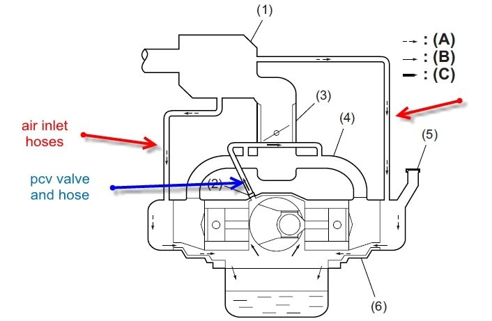
You mention Porsche, which we have worked with closely over the years and here is the 911's PCV diagram to show:
The red in this diagram is the "fresh" or "clean" side, the blue the dirty or foul side. The reason you find pressure when opening the oil fill cap when running is due to the poor PCV system design allowing all that pressure. NO engine can run at peak efficiency fighting crankcase pressure, and if you look at the N14, the dirty side is run directly to the intake manifold so at idle should pull reasonable vacuum.
I can provide all the technical papers and diagrams, but it appears your mind is made up based on assumptions, and not the actual technical design. I don't want to fight, that helps no one, but this is my specialty for decades and am involved in design work today for tier 1 suppliers to the Big 3 in the US and several in Europe as well as author articles for several automotive based publications along with heading up SAE member discussions. There is no "winner" in this argument as far as your belief and my facts...this is just to educate.
If you see a balloon inflate that is a BMW service tech simple test to diagnose a failure or obstruction in the PCV system:
"With the oil cap sealed, engine on, stick a balloon over the dipstick tube and see if it inflates. If it inflates you need to service the PCV system."
What you seem to really be stuck on is the outgoing vapors pulled from the crankcase must ALWAYS have incoming replacement fresh are on ALL PCV systems. That has never changed in automotive history of the PCV system.
If your not flushing the damaging compounds from the crankcase, your allowing most of it to remain in and mix with the engine oil.
Originally Posted by donniedarko
Had fun with it. Buddy works for Holley flowed me the AN fittings, Mr Saikou made me the ends to assume the AN kit. The SamCo silicon hoses are stuff I had laying around from my sportbike. The install was tough as the can are considerable. The AN fitting required me to lower the mounts, I used to clay to see if they we're hitting the bonnet and they were. In the end very satisfied. $218 in total had I paid for the stuff twice.
I'd like to get the AEM strut tower and feel it will bolt on. As always we'll see.
This is very common. You have defeated all evacuation and mixed the clean and dirty sides into a vented can it appears. Now you have stopped the oil, but at the sacrifice of engine longevity.
If you do not evacuate (suck out) the damaging combustion by-products entering as blow-by while still in a suspended state, they quickly fall out of suspension and mix with the engine oil. Once there, it is wear.
One more white paper on all of this (but specific to GM. Still the same principles and issues):
Understanding the differences between Port injection engines of the LS family, and Gasoline Direct Injection of the new LT family of engines:
Back in the days of carburated engines, the air and fuel were mixed in the throat of the carburetor, and the A/F mixture then traveled down the intake runners and into the intake port of the cylinder heads. Then during the intake stroke of the piston, this mixture was drawn into the cylinder where it was compressed during the compression stroke and then ignited by the spark plug. In those “old days” it was common to expect to need a “valve job” at 30-40k miles and this was to manually clean the deposits that would form on the back sides of the intake valves and replace the guides that were worn out of acceptable tolerance's by these deposits that were drawn into the guide with each cycle of the valve.
Along with this, the valve was “dressed” and re-lapped to the seat, and if the seat was worn or damaged, it was replaced as well. To help to combat the severity of these deposits, the Federal Government mandated that ALL gasoline sold for street use contain a minimal amount of detergent additives, but this only reduced the severity. So any “old timer” mechanics remember the valve job. Then along came port fuel injection (we will skip TB injection as it was little different than a carburetor as coking issues are concerned). Port fuel injection moved the fuel introduction down into the intake manifold runners, and right before the intake ports of the cylinder head. The fuel injector now directed the fuel flow directly into the port, and the backside of the intake valves. The pressure for improved atomization was increased to 45-55 PSI, and this detergent fuel (Top Tier fuel include additional additives beyond the mandated minimums) constantly cooled and kept the valves clean and deposit free. One of the many advantages over the ancient carburetor. In fact anyone that has torn a LS based engine down and examined the valves has seen zero deposits where the fuel spray made contact, even at 100-200k miles of use, and top tier fuels were even better at also helping to keep the fuel injectors clean and deposit free. These deposits of old were the result of the oil mist and other combustion by-products that are present in the PCV vapors would “bake” onto the backsides of the valves and build deposits over time. And with the introduction of port fuel injection, this no longer raised it's ugly head.
Here is a photo of how port injection operates to illustrate this:
As you can see, the placement of the injector directs the fuel to spray directly onto the the valves and not only cleans and prevents deposits from forming, but also keeps them relatively cool also making it difficult for deposits to take hold.
So, good bye to the “valve job” as we old timers knew it. In fact, the average Dealer service and repair tech most likely has had little to no experience with this as for the past 20-25 years, as it has rarely been needed and not taught either.
Or so we thought, until the industry began to embrace GDI, or Gasoline Direct Injection (diesels also use Di but we won't go into that here). The advantages of GDI are many, and help our automakers to accomplish several things. That being more power from smaller displacement engines, better fuel economy due to greater efficiency, and the reduction of detonation or what most know as knock retard. Lower tail pipe emissions (at least when new) are also a benefit.
The power comes from the ability to run far higher compression ratio's with 11.5:1 and higher not uncommon, and in passenger vehicles to also run 87 octane fuel (the Corvette runs more aggressive timing advance so premium is highly recommended).
The reasons we can now run compression ratios that back in the day of port injection would require race gas, is the elimination of any fuel or combustible being present during the compression stroke. With GDI the fuel is introduced directly into the combustion chamber, and not until the final milliseconds of the compression stroke before ignition. To do so, the operating pressure of the fuel has now taken a huge leap up to 2000-3000 PSI vs the old 45-55 PSI. This also keeps the injectors, in theory, deposit free for the life of the engine (and in practice although we do see a failed injector on occasion, we have yet to see clogged ones so it appears fairly accurate). So, this means in tank additives and running top tier fuels have absolutely NO effect on this issue of intake valve coking and the related wear and problems. All gasoline comes from the same bulk distribution tanks, and the “top tier” additives are then added, so if they never touch the valves, there can be no benefit from the use.....but even knowing this I still am loyal to Shell, etc.
So, the fuel is atomized at a far more efficient amount and the burn is more controlled and complete producing more energy per explosive event thus providing more power and better fuel efficiency.
You will also note the topography of the piston top is far different than the conventional port injection flat top piston. The center section is pretty much the only area that touches the fuel, in fact GDI is so efficient most of the burn is completed BEFORE the fuel makes contact with the piston top.
So, now that we have covered the advantages of GDI, and they are many, we now come to the disadvantage, and this is a pretty big disadvantage as the more time goes by, and the more “real world” examples we see, the more this one issue rears it's ugly head, and that is intake valve coking. Now, most everyday drivers of a newer GDI vehicle will not be aware of the issues related to GDI as the degradation is gradual and accumulative.
And many will claim this is “fear Mongering”, but that facts are there for anyone to see that wishes to dig a bit, and that is on your own C7 if mechanically inclined. It is as simple as removing the intake manifold and the intake valves are right there to examine up close and personal.
Here is a LS1/6 engine with 143,000 miles (my own C5) and top tier fuel back then was rarely used, but look close. Anywhere the fuel spray made contact, zero deposits:
Note the “mushroom” of deposits as the valve cycles into and out of the guide and scraps most of it down, some is also pulled into the guide and as this develops it becomes very hard and crystallizes due to the much higher temps the valves now operate at, and although this is just beginning, by 8-10k miles the tulip and main portions of the valve have already developed severe enough deposits to disrupt the airflow into the combustion chamber. In fact, here is an example of a GDI owner (not a C7 as we have not had them long enough to compare as this owner did, but he began having dyno runs done each year, at approx. the same time, on the same dyno, and the same SAE correction factor. He did not begin until the car had 15k or so miles on as you can see, and then put 15-20k miles a year on for 3 years of documenting (this is NOT a C7, but is a newer vehicle with the same GDI technology as the LT1). When he did the final dyno, he performed a manual intake valve cleaning procedure and did a additional run to show the power lost over that time. As it was gradual, he did not really notice, but after the cleaning the power is restored to the level as new:
Most are the oil most and other combustion byproducts that are constantly present in the PCV vapors that are evacuated from the crankcase. The oil mist is from the windage of the engine rotating, etc. and the other compounds are what every internal combustion engine has entering as blow-by. These are water, un-burnt fuel, sulfuric acid, and carbon and soot particles and other hydrocarbon based compounds. These MUST be removed from the crankcase as soon as they enter and are still in a suspended or gaseous state.
If not removed by the evacuation and flushing functions of the PCV system, these would quickly settle and mix with the engine oil greatly increasing wear and shortening engine life. These are evacuated, or “sucked out” the PCV barb located in the valley of the LT1/LT4 engines. Clean, filtered and MAF metered air drawn in from the main intake air assembly where they make up for, and flush the foul vapors out. With the wet sump LT1 this is into both valve covers at the front of each directly from the air intake assembly, and with the dry sump it first enters the dry sump oil tank and then is split out and enters both valve covers. With the LT4 it also splits and enters both valve covers. The intake manifold vacuum is what is used to evacuate these damaging compounds from the crankcase and that is how they make contact with the back sides of the valves.
Many have already seen the Z51 for 2014 that allowed much of this oil to enter via the “fresh” or “clean” side of the PCV system during acceleration due to crankcase pressure building as intake manifold vacuum drops to zero from the reversion pulses present due to valve overlap. If the dry sump tank was filled to the initial level on the dip stick, it was really “over filled” and made this “burping” of oil backwards into the air assembly as shown:
For 2015, GM implemented a greatly improved “cyclonic separator” with the sump tank and also lowered the proper fill level and reduced most of this, but not all. The wet sump version also has this issue but not as severe.
But most of this oil and “gunk” mix enters via the PCV barb from the valley. These compounds are what are now baking onto the valves and as these run so much hotter than port injection, not only is the amount far greater than ever before, the damage caused is also showing as miles accumulate in excessive wear to the valve guides. This is NOT the soft carbon of the past that a Seafoam or similar upper induction cleaning could remove effectively and safely, these are very hard crystalline deposits that become very abrasive when broken loose, and thus the wear of the valve guides over time.
While in the beginning, most will not notice and degradation in power, running, etc. until the deposits reach a level where they are disrupting the incoming air to the point of unequal A/F mixtures in each cylinder. The cylinders closest to the int of ingestion will build deposits more rapidly and more severe than those furthest form this ingestion point. As the fuel amount commanded by the PCM is based off of data from several sensors, and the upstream O2 sensors being the last to determine the A/F ratio samples all 4 cylinders on that bank as a whole, the cylinders with the most severe deposits will run richer as less air is entering and each injector is commanded to deliver the same amount of fuel as the rest on that bank. The cylinders with the least amount will run leaner than intended so the more severe the deposits over time, the more degradation in the power and efficiency of this marvelous engine. Remember, the valves and ports were designed by the engineers to flow as efficiently as possible, and as these uneven deposits build and form, this is totally disrupting the intended flow and velocity of air into the chamber.
The most evident symptoms are hesitation off idle as you accelerate. This is when the deposits are fairly minor and as the flow rate increases with RPM's and throttle opening, it overcomes the disruption so at WOT there is not much noticed. As the deposits build in severity, random misfires may trigger a CEL, and MPG and power definitely degrade (I invite any to dyno your C7 when break-in is completed and rings are seated to establish a baseline and then every year, return to the same dyno and use the same correction factor as the example earlier and you can document the power degradation as proof)
As the miles accumulate, the deposits increase in severity and it is not long before a good portion of the valve area is completely covered as shown:
And this is where the valves begin to become less stable at higher RPM's as the guides wear out of factory spec. (see the LS7 issues from improper machining..this is far more common).
Fuel economy continues to degrade as does power and for the “seat of the pants” owner, drive ability also begins to suffer.
Once these deposits reach a level such as the last picture, a large “*****” of this can break loose and get trapped between the valve and seat allowing piston contact with the valve, and a bent valve is the result.
As you can see in this example, that is just what occurred here:
The owner noticed the engine was not as responsive and powerful as it had been, and brought it to the dealer (under warranty) and was told “no trouble found”. He persisted and finally after several visits they performed a compression test and found this cylinder lower than the rest. As you can see, he drove quite a while after the issue occurred so deposits were already re establishing over the area the piece came from. Again, this is not our old “get the carbon out” type of deposit. These eventually turn very hard and brittle and become very abrasive when broken loose. And that we will cover in the solutions portion of this article.
So, now we know what occurs, and how widespread it is (every automaker in the World is experiencing these same issues, and none admit it exists and all claim they are not effected by it, but it only takes a few minutes of examining your own GDI engine to see it first hand).
So, what is the industry, and more importantly GM doing to combat this and reduce what is occurring? Well first, do not think GM has betrayed you as all automakers have had to adopt GDI technology to meet every more stringent CAFE fuel economy standards as well as tail pipe emissions reduction. GDI does this. Aside from MOPAR, Ford is the only one still offering port injection in their V8 engines and after 2017 it is rumored all will have made the jump. There are several areas GM has really made progress, and that is in the internal air/oil separation, and no where is this more evident than in the LT family's valve covers.
Never has GM had such a robust and effective design and here is how they have accomplished this. Note there are several “humps” or risers in the valve cover. As the PCV system as it comes from the factory only utilizes intake manifold vacuum for crankcase evacuation to remove the damaging combustion by-products we went over earlier, when you accelerate, and especially at WOT, the intake manifold vacuum drops to zero. So crankcase pressure builds during this time and it seeks the path of least resistance to equalize, and that is “out the in” or backwards, out the fresh, or clean side of the system. The PCV system performs far more critical functions than just pollution control. Back before the PCV system was mandated in the early 1960's, all engines just “vented” to the atmosphere. Generally through a road draft tube. At this time, the average oil change interval was 1500 miles. The average engine cared for properly could last 40-50k miles before extensive wear required a complete rebuild. But in the years following the Federal Mandate (which was for pollution reduction only at the time) it was found that these same engines, running the same oils, and same 1500 mile change intervals were now lasting 100-150k plus miles before needing to b rebuilt. It took awhile to determine why this was, and that is where the damaging compounds that used to be left in the crankcase and accumulated wearing the engine were discovered. The PCV system was now removing them before they could settle and mix and accumulate in the crankcase and engine oil where in the past when the crankcase was just vented, these mainly remained in the crankcase quickly contaminating the engine oil causing the wear all had thought was normal. As most of the wear is caused by particles smaller than the 15 microns the oil filter today traps down to, they remain in the oil, and so you NEVER want to defeat the functions the PCV system perform as more are doing in an alarming number without realizing the consequences of this. Your PCV system can be enhanced to be even ,ore effective at evacuating these compounds and also to pull suction at all times eliminating the periods during acceleration when evacuation halts, but to defeat ANY of the functions is NOT the answer. Stopping the compounds causing the coking can be effectively accomplished and emissions compliance retained. We will go more into this later. Back to GM. Here is the new valve cover:
The raised areas are condensation and separation chambers. They use a coalescing screen and gravity to separate some of the mist form the vapors and also have a greatly improved lower baffle to prevent oil splashing directly into the backsides from the rocker arms. Inside we can see how this is accomplished:
Now, this is on the fresh or clean side of the PCV system where during acceleration and WOT pressure forces these vapors to travel backwards and out into the main intake air assy. So they have done an awesome job here. Further, the baffle located underneath the valley is also improved and more effective, and the new cyclonic separator for the dry sump is a home run. (those with a 2014 may be able to upgrade to the 2015 version under warranty. If not it is highly recommended you do this swap).
GM also has now included an integrated one way check-valve in all LT based V8's, something only a few of the “catch can” companies had done in the past. This helps to reduce the amount and gives only one path now for these vapors to travels backwards during acceleration. All ads up to a great job in internal air/oil separation, but here is what has occurred. Separating the oil mist internally allowing the oil to remain in the crankcase has also reached the effectiveness point where these improvements are also retaining more of the damaging compounds that must be removed, and anyone with a GDI LT engine h=just has to check their oil dip-stick to see visually how quickly the oil turns dark after a change. This is due primarily to the abrasive soot and carbon particles that are now being retained in a much greater amount than in the past along with the other contaminates, and only time will tell how much this will impact the engine life. So, I believe the “wall” has been reached in internal separation.
Other area's changes have been made, but they in real life have far less positive results than anticipated. These are multiple fuel events and valve events that are designed to allow some fuel to again contact the backsides of the valves, but this has a side effect that IMHO outweighs any benefit, and that is fuel being present during the compression stroke is now allowing an increased incidence in detonation and thus knock retard. KR is when the PCM receives data from the knock sensors indicating detonation is occurring. The knock sensors have the ability to detect knock before the human ear can, and the PCM will pull ignition timing until the knock has ceased. If you are not running optimum ignition timing advance, the engine is not producing the power and economy it will when running at optimum settings. So this is taking away some of the benefits of GDI, and the actual effect on slowing the deposit formation is minimal by itself, but in conjunction with the improved internal separation GM has made some real improvements over the previous L4 and V6 GDI engines of their past.
Others have also added in small port injectors again, but this results in even more detonation so this is not enough to clean the valves, and is more fuel than can be present to take advantage of the principal of GDI.
So, the near future does not appear to hold much additional improvement. The only way to stop this from happening is to effectively trap and remove the oil and other contaminants form the PCV vapors, and further to enhance the evacuation function of the PCV system so it is always utilizing a sufficient suction source at all operating levels, and this is where Elite Engineering's new E2-X line of true air oil separating systems. The average “catch can”only traps 15-30% of the oil and other contaminants that cause the coking.
This was fine with the old port injection engines as they could tolerate a reduced amount of ingestion quite well. Enter GDI and Elite Engineering USA saw the need for a completely new design that actually addresses all the causes that allow the average catch can to “pass through” more oil than it can catch. And no matter the cost or the name brand, this is true across the catch can market. Elite has produced a system that addresses not only the effectiveness of separation to 95-98% effectiveness (the only more effective solution is a centrifuge based industrial system) and also allows for constant evacuation suction so no longer is the PCV system only operating properly when not accelerating. The E2-X systems provides a secondary suction source and dual inline billet check valves that automatically open and close to always utilize the strongest suction source eliminating the times when crankcase pressure can build and force flow “backwards”. It also includes a billet “clean side separator” to trap any oil mist that may attempt to backflow during the brief periods the valves are switching maintaining a closed, emissions compliant system.
The average catch can has only one suction source, the intake manifold, and as they trap such a small portion of the entire amount of oil and other contaminates there are few true solutions for the GDI engines of today. And going forward Elite has also has developed a OEM capable solution that does not need to emptied or serviced for 100k plus miles and with patent pending, this may be the answer in the future.
Now, what about the solvent based upper induction cleaners used while the engine is running?
In the past as the deposits were mainly soft carbon build up on the piston tops and combustion chamber, these were a relatively safe and effective way to clean those deposits. But now with the severity much greater, and these deposits being on the backsides of the valves and also the very hard and abrasive nature, if performed along with the proper air/oil separation system such as the Elite E2-X series, using an upper induction cleaner every 15k miles can be one of the best ways to keep these deposits to a minimum and have minimum effect on the engines life and performance. So used properly these are now a highly recommended regular part of owning a GDI engine, but!
And this is a BIG but. IF you allow the valves to reach the pint that the deposits have built to excess and enough time has lapsed to turn the deposits to a hard crystalline state damage can (and does) occur! The rule of thumb with the LT based V8 is 10-15k miles. If you have more miles than this here is what we have found (and I know, all of these companies claim these are safe to use, but when we tear these engine down after the use we find the following):
The solvents work by soaking into the deposits and expanding then so a portions breaks loose and are then expelled out the exhaust port. 2 things, with established deposits we rarely see more than 50% of these removed from a treatment. Then smaller particles are forced between the piston and the cylinder wall, and if these are hard and crystalline, this causes scouring (scratches) in both the cylinder wall and the piston sides and skirts. Although most of these scratches are minor, I prefer no damage as this is only the start of more severe scouring and eventually increased blow-by and other issues. Then, we are also seeing a higher incidence of catalytic converter damage as the larger amounts of these deposits and the solvent make contact with the red-hot catalyst strata can cause it to break and clog. In a turbo equipped engine, damage to the leading edge of the hot side turbine blades is common and Ford and others do NOT allow these treatments on GDI turbo equipped vehicles. So, unlike the old port injection engines that many use these with great results, one must use caution with a GDI engine. Ideally, you will install a proven system like the E2-X series and then every 15k miles perform an upper induction cleaning service paying close attention to the instructions, and you should not have to worry about these issues.
The following are additional pictures:
What the average LT4 looks like run as it comes from the factory:
That video is still the only real accurate training video readily available or I would have linked to a better one if available.
To compare qualifications, I have worked as an Automotive Engineer for over 4 decades, a wall of certifications and degrees, etc. as well as being a member in good standing of SAE. Not to take away from your experience, but it appears we agree to disagree here. I work from the industry side for decades and design PCV systems for many auto makers applications (all 2014 and up GM GDI V6 engines have one of my personal designs in every 3.0 and 3.6L today). ALL have fresh and foul, that is plain fact even though you are correct in your ballon test. The reason you see this is the poor design of the BMW PCV systems allows so much crankcase pressure and also BMW is known as one of the worst offenders in intake valve coking due to these poor designs.
You mention Porsche, which we have worked with closely over the years and here is the 911's PCV diagram to show:
The red in this diagram is the "fresh" or "clean" side, the blue the dirty or foul side. The reason you find pressure when opening the oil fill cap when running is due to the poor PCV system design allowing all that pressure. NO engine can run at peak efficiency fighting crankcase pressure, and if you look at the N14, the dirty side is run directly to the intake manifold so at idle should pull reasonable vacuum.
I can provide all the technical papers and diagrams, but it appears your mind is made up based on assumptions, and not the actual technical design. I don't want to fight, that helps no one, but this is my specialty for decades and am involved in design work today for tier 1 suppliers to the Big 3 in the US and several in Europe as well as author articles for several automotive based publications along with heading up SAE member discussions. There is no "winner" in this argument as far as your belief and my facts...this is just to educate.
If you see a balloon inflate that is a BMW service tech simple test to diagnose a failure or obstruction in the PCV system:
"With the oil cap sealed, engine on, stick a balloon over the dipstick tube and see if it inflates. If it inflates you need to service the PCV system."
What you seem to really be stuck on is the outgoing vapors pulled from the crankcase must ALWAYS have incoming replacement fresh are on ALL PCV systems. That has never changed in automotive history of the PCV system.
If your not flushing the damaging compounds from the crankcase, your allowing most of it to remain in and mix with the engine oil.
This is very common. You have defeated all evacuation and mixed the clean and dirty sides into a vented can it appears. Now you have stopped the oil, but at the sacrifice of engine longevity.
If you do not evacuate (suck out) the damaging combustion by-products entering as blow-by while still in a suspended state, they quickly fall out of suspension and mix with the engine oil. Once there, it is wear.
...
Last edited by donniedarko; 03-17-2016 at 06:24 PM.
Some folks must not be too busy and have way too much free time
Who the hell is going to read that diatribe above??
You're losing the focus.....and distorting the facts. Let keep it on Mini for kicks.
The "fresh air inlet" is only at idle OR decel throttle closed Thats it. Further ingres is limited by a PCV like check valve on the "fresh" air side.
The idea of gases in oil is greatly over exaggerated. Especially if u have a "healthy" engine.
Otherwise......change the oil often as one should then!!!!!.
Only pressure is created in the crank when engine is really operating i.e. not at idle or decel!!!
No air will ever enter the crank under these conditions; other than idle or decel. Beside it enter the top of the motor where it NEVER gets into the crankcase.
Why...???? Because there is NEVER any vacuum to pull it down there.
Why..???Again, because the motor has either 1) no vacuum when throttle is open to evacuate the crank (it will never draw air in) or 2) there is pressure (see turbo) in the intake and crankcase ((better have that 1 way check valve working)) i.e. the n14 motor which is what part of this forum is about. No a chevy, chrysler bla bla bla
To call that drivers side vent an inlet is mostly specious; yeah only a tiny bit at either idle or decel. Again, it only send air exactly where it is not used or needed; at the upper most region of the motor
Infact, IMO it actually hurts the scavenging effect by adding unneeded air that just dilutes the CC vapors, which I guess is better for a motor with an inferior CC oil separation system but if one is trying to evacuate the CC, then why add more volume especially if we are employing OCC which is what this thread is about??
I saw your video and have a better understanding of what I am dealing with. Suggestion; if u r going to show a mock up then at least mock it up.
Cannot waste anymore time here really.
All the best
Ciao
Guys I need help, losing my damn mind trying to figure this out. So I soda blasted my valves and installed the rx racing OCC, correctly I'm fairly certain, but When I start the car it runs fine for a moment but then once it settles the idle alternates from 1000 to 1250 repeatedly, like some ******* at a red light impatiently tapping the throttle, except nonstop. It's practically undriveable, I might be able to limp home.
Is there some part of the factory pcv system I'm supposed to defeat in order for the occ system to function properly? It definitely seems like some kind of pcv issue but I can't seem to figure it out. God I hope one of you guys know what the eff cause I'm at my with end and just want to go home and shower
Last edited by WrenchMonkey; 03-18-2016 at 04:40 PM.
Guys I need help, losing my damn mind trying to figure this out. So I soda blasted my valves and installed the rx racing OCC, correctly I'm fairly certain, but When I start the car it runs fine for a moment but then once it settles the idle alternates from 1000 to 1250 repeatedly, like some ******* at a red light impatiently tapping the throttle, except nonstop. It's practically undriveable, I might be able to limp home.
Is there some part of the factory pcv system I'm supposed to defeat in order for the occ system to function properly? It definitely seems like some kind of pcv issue but I can't seem to figure it out. God I hope one of you guys know what the eff cause I'm at my with end and just want to go home and shower
I had a hose loosen and the same thing. Threw a CEL. Was tripping out like you thought I broke my car lol. Pulled over hose at the PCV side was loose. Went through the lines and secured the hose clamps and car runs great. After turning the car on and off the CEL light went off too without and ODBII reset...
 03-07-2016, 10:51 AM


 this is to much......