When you click on links to various merchants on this site and make a purchase, this can result in this site earning a commission. Affiliate programs and affiliations include, but are not limited to, the eBay Partner Network.
Can you use a threaded insert and a standard nipple for the PCV, Breather, and MAP sensor connections to make it easier?
The MAP sensor will not be affected as it is not connected with the charge pipe ( except if you mean something different and I did not catch you )
Now for the PCV you mean threaded insert on the machined adapter or the filter element?
I have two thoughts:
Heatshield:
I use the machined adapter as a billet piece with a tapered design, nothing is threaded but it is a united body.
Airbox:
If the space is not available for the adapter I will use another filter element for the PCV line. Because everything will be closed, oil smell will not come inside your cabin when you use your aircon. ( To be honest I want to avoid that solution)
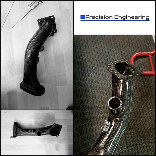
Hello guys, finally the prototype is ready!
I finished the installation late last night. I will update the thread shortly with some pictures from the installation. So far everything went according plan. Fits perfect, no contact at all with other components ( so no need for the spacer), no air leaks and smooth operation.
And just a small teaser
Hello guys . The last 3 days I am driving the MINI with the charge pipe, no problems at all everything seems nice! I am pretty excited so far, it turned out to be better than I thought. I dont want just to say things thats why I will wait for data to present to you. I played a bit with a video so you can have an idea how it sounds. Its just a small clip. My editing skills are not perfect, so please be aware of that. If you are curious of what program I used, it is Vegas Pro 14. Pretty nice video editor, first time tried and I am very happy with it.
So what your thoughts? Do you like the sound (its a small clip I now) ? Any comment or question are welcome.
The MAP sensor will not be affected as it is not connected with the charge pipe ( except if you mean something different and I did not catch you )
Now for the PCV you mean threaded insert on the machined adapter or the filter element?
I have two thoughts:
Heatshield:
I use the machined adapter as a billet piece with a tapered design, nothing is threaded but it is a united body.
Airbox:
If the space is not available for the adapter I will use another filter element for the PCV line. Because everything will be closed, oil smell will not come inside your cabin when you use your aircon. ( To be honest I want to avoid that solution)
If I missed something correct me.
Originally Posted by P.E
Hello guys, finally the prototype is ready!
I finished the installation late last night. I will update the thread shortly with some pictures from the installation. So far everything went according plan. Fits perfect, no contact at all with other components ( so no need for the spacer), no air leaks and smooth operation.
And just a small teaser
He eliminated the PCV connection (one closest to the supercharger).
Jan brings up a good idea, you should monitor the map sensor off the inlet closely to see if there is a significant change in vacuum.
I would plumb the PCV connection into the filter housing like you were discussing. It should have vacuum to function normally (how PCV valves are designed to work) but not as much as they see right in front of the supercharger inlet in the stock design.
Great work, looking forward to seeing the dyno and data logs on this.
I would not expect one can discern the increase or decrease of torque/horsepower on a dyno with this change. How do you control all the extraneous variables that you have no control? And what about the repeatability of the typical initial dynos at this granularity?
Sorry guys I think I did not make my shelf clear. I do not eliminate anything ! Is that you are saying? ( Maybe I did not catch something, it is my English I am sorry)
If you see the charge pipe there are to aluminium take offs, these are connected to the vacuum lines as the OEM unit. Additionally a breather adapter is attached between the air filter and the throttle body. So everything is as it was from the factory.
Ok, that's what I missed, because you changed the connection style of the crankcase vent/breather.
My bad.
I would not expect one can discern the increase or decrease of torque/horsepower on a dyno with this change. How do you control all the extraneous variables that you have no control? And what about the repeatability of the typical initial dynos at this granularity?
I will use the dyno only for the delta factor. It is not the only test I am planning to do.
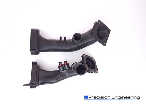
Hello to everyone. I could not update the thread for a while as I was abroad for some days.
I took a photo yesterday with the printed model and the OEM component so everyone can have a better idea.
Hello to everyone. I could not update the thread for a while as I was abroad for some days.
So nice to see someone use a now quaint word "abroad".
I know how much work this project is. Since you raised the throttle body have you provisioned yet for the structural support that is the equivalent of the OE steel bracket? Sometimes the little things are the hardest to take care of but reliability relies on it, even for a DD. May be I am getting ahead of your plan which would be how I would deal with it as a back-burner issue but not to be forgotten.
Yeah I have considered what you mentioned. So if you take a closer look at the last foto you will see the flange that the throttle body seats has 6 total holes. 4 for the actual throttle body and another 2 above them. These two will be used for the support bracket. The support bracket would extent to the OEM support bracket mounting points. So I am planning using the OEM support points. I have not finish the support yet (it's half way there) , my plan is to finish it in the next couple of weeks. I am thinking of using carbon fiber again. As I have done some brackets from carbon fiber for a motorcycle exhaust in the past and it looks amazing (plus it is functional).
More updates:
I am waiting for the correct air filter to arrive ( should be these days), because now I am using an old one (and out of specifications for the application). I bought some meters of vacuum lines in black colour as now I am using blue ones which I dont really like !! Heat shield 3d printed model should be ready by Friday. After installing all these I will take some proper fotos, so everyone can have a better idea about the kit.
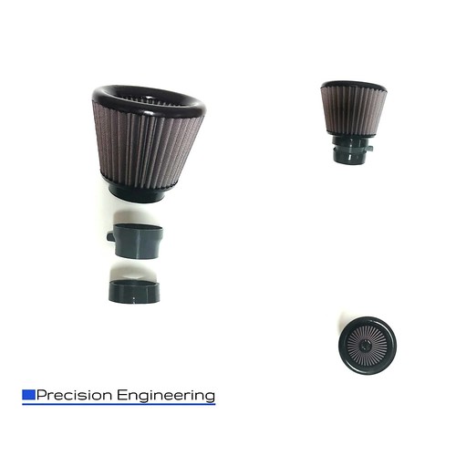
So I did some test fitting yesterday with the air filter, I had a small problem with space but I think I have a solution for that.
Below you can see the air filter with the adapter (printed model). So the the only thing I will change is the high of the adapter. Thus there is no room for the breather tube! Of course I do not really like that idea, thus the breather line will be connected on the top of the air filter. I already designed an adapter, and I am waiting the printer to finish (photos when I will have it ready).
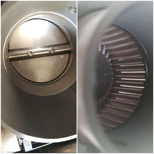
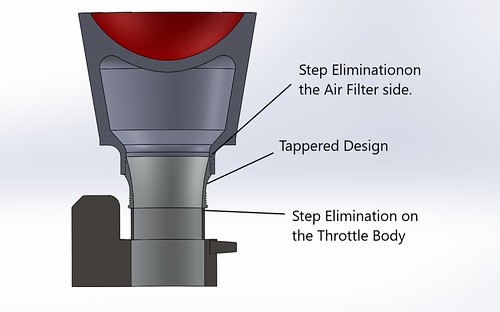
The reason I chose this air filter is space. The space is very limited so the air filter has to be as short as possible. On the other hand I wanted to achieve a specific ltr/min number ( 7000 + ltr/min or 250 + cfm). In the second photo you can see the tapered design of the adapter and the elimination of the step on the filter and the throttle body side. I wanted a smooth transition from the air filter up to the supercharger inlet. In the third photo is a bit more clear what I am describing.
if you are so worried about choking off the inlet to the supercharger why didn't you just design the inlet pipe with a 3" throttle body and run a bigger pipe design?
I'm going to ask again , what was the vacuum on the inlet pre-supercharger at idle and redline?
if you are so worried about choking off the inlet to the supercharger why didn't you just design the inlet pipe with a 3" throttle body and run a bigger pipe design?
I'm going to ask again , what was the vacuum on the inlet pre-supercharger at idle and redline?
It is possible to use a 3 inch throttle body. But the design changes a bit in the upper section. I can not include in the kit a 3 inch throttle body as the cost is already to high. But if someone wants a 3 inch throttle body it can be done no problem at all. The design can be taylor made for a specific application but I wanted something that utilises most of the OEM components.
The main idea is to keep the id constant as much as possible. There is no more room in the lower section ( supercharger inlet) to increase the id of the pipe (I really used every available mm there). But there is a significant increased compared to the OEM design.
About the vacuum on inlet pre-supercharger at idle and redline ( apologise I miss your first question) I do not have any data. I am in the stage of collecting data. My main concern was to finish the prototype and see if it is possible to make something like that. Then if it seals and actually works. I try to avoid saying how it feels as I do not have data to back up my words (lets say I am very very happy) and I want to be clear with what I am saying. But you have a strong point and I totally agree with you. It will take a bit more to colect all the data, as now I am more focus on the heat shield and some other details that are crucial.
To P.E: Please regard this post as a design review in which the presented ask questions.
Until today, I paid little attention to the supercharge air paths and the extreme challenges the engineers faced with packaging the SC into the confined engine bay. Looking at the peculiar shape of the stock plastic charge pipe, and your alternate design, I cannot help but to wonder the reason behind the rather "distorted" appearance of the stock pipe.
At first glance, I immediately assume it is shaped to fit into a space so not to interfere with other stuff that competes with cubic mm. More careful observation tells otherwise, if I have not mistaken. There is almost no reason for the crushed depression on the leading vertical surface as it is not right against anything.
I have two thoughts as to why it is the way it is, rather than making it circular tube like almost end to end:
1) The engineers had conducted flow analysis taking into account of the air stream that may consist of quite a bit of spiraling due to the two screw-like rotor scrolls. The result is charge tube that is twisted. Further, as the SC intake port is a flatten oval the charge tube also transitions from circular on the throttle body into a flatten oval when it reaches the SC intake port.
note the flatten and twisted shape of the charge pipe
2) Could the flatten shape of the charge pipe and the dimple is there for acoustic reason - to give the coolant fan back side more space? More space behind the high CFM fan so it won't be so loud and annoying? You don't need to be an engineer if you ever mess with computer cooling fans to know this.
As I scrutinize the stock charge pipe closer, the more I am convince it is done for the reasons in (1) I outlined.
That depression is there for clearance. I believe to the fan shroud. You have to keep in mind that the OEM has design clearance rules. For a part like this, it was probably full engine translation (such as under 1G braking) and roll +6mm. That kind of shape would never be done for noise. And they would have to consider all variants of the vehicle, so if there is an upgraded radiator/fan for example (I don't know that there is), the part would have to clear it as well.
I do appreciate the skill and hard work it takes to take on a project like this. Likely though that gains will be very small.
Space clearance of more 50 mm in some specific areas? The OEM design is like that only for noise reasons. MINI has to sell the car not only to people that they want to drive fast. Supercharger whine for automotive engineers is disadvantages ! it is not acceptable having a lot of noise inside the cabin or outside the vehicle. Also I realise that the comment you quote say's that the fan will make more noise. I drive the car now everyday with the charge pipe on for the last nearly 4 weeks. In the mornings I drive usually in heavy traffic with outside temps of 35C..... So the fan works a lot. The noise levels of the fans are exactly the same.
I haven't update the thread for a while I am aware. The printed model of the heatshield is ready but there are some mistakes with the print so I will print another model next week.
 05-31-2018, 08:25 AM