Drivetrain My build. Teaser photos and updates
#326
 06-03-2014, 06:39 PM


well i am pulling it all together. Looked at welding one up with a core, but bell only sells water to air and air to air cores. (oil uses different passage styles typically)
So I will probably just be buying a vacuum brazed aluminum construction one from earls or something.
Thought about dry sump, but to much money, not enough gains for my style of driving at this point. (and where in the hell would I put the reservoir. )
)
So I will probably just be buying a vacuum brazed aluminum construction one from earls or something.
Thought about dry sump, but to much money, not enough gains for my style of driving at this point. (and where in the hell would I put the reservoir.
)
#327
06-04-2014, 04:50 AM

#328
06-06-2014, 05:44 PM
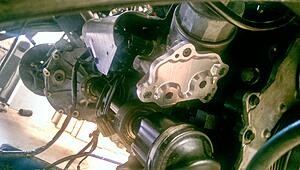
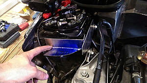
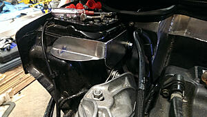
here she is!


I cheated a little on the finishing passes and will just smooth them out by hand with a dremmel, but eh. most of it is cosmetic. Still pretty i think
and mounted!
Still need to weld on the AN fittings (on order), oh, and dont tell anyone, but I totally just guessed on the head clearance on the back side cut for the bolts. Guessed right I suppose considering they clear, but just barely!
Last edited by soccerbummer1104; 08-27-2014 at 08:18 AM.
#330
06-07-2014, 04:55 AM
#331
06-07-2014, 05:51 AM
while technically ignorance is simply the act of not knowing something, and your question by default is founded in it, It is still a good question! 
to answer your question in general:
MOST CNC machines will, the method about which they do it varried depending on the method and age of machine, but that was one of the original purposes of CNC.
Old school methods were you had a list of default commands, but a lot of the mill in terms of touching off, reference points, etc, was all done by hand. Usually with someone with a dial, and a button to change axis, and then a command to say "okay, cut this circular pocket 1" deep". And while they were doing all of these steps, the machine was recording the motions to tape, so the next time you want that part you load in the tape and the machine repeats the steps as you did them.
Things have progressed a bit since then, and now a lot of the tooling paths can be done inside of solidworks, or a g-code software such as mastercam.
These are very nice, but take a while to set up, as for a lot of things it is still based of of the "old school" way of thinking, and not a "I will give you some input and you determine the best way.
A lot of this comes down to the fact that the machinist using the software knows what tools they have on hand, or what tools he will need to grind from scratch to make the cuts in as few passes as possible.
And since it is all digital, it is saved
Last edited by soccerbummer1104; 08-27-2014 at 08:19 AM.
#332
06-07-2014, 06:22 AM
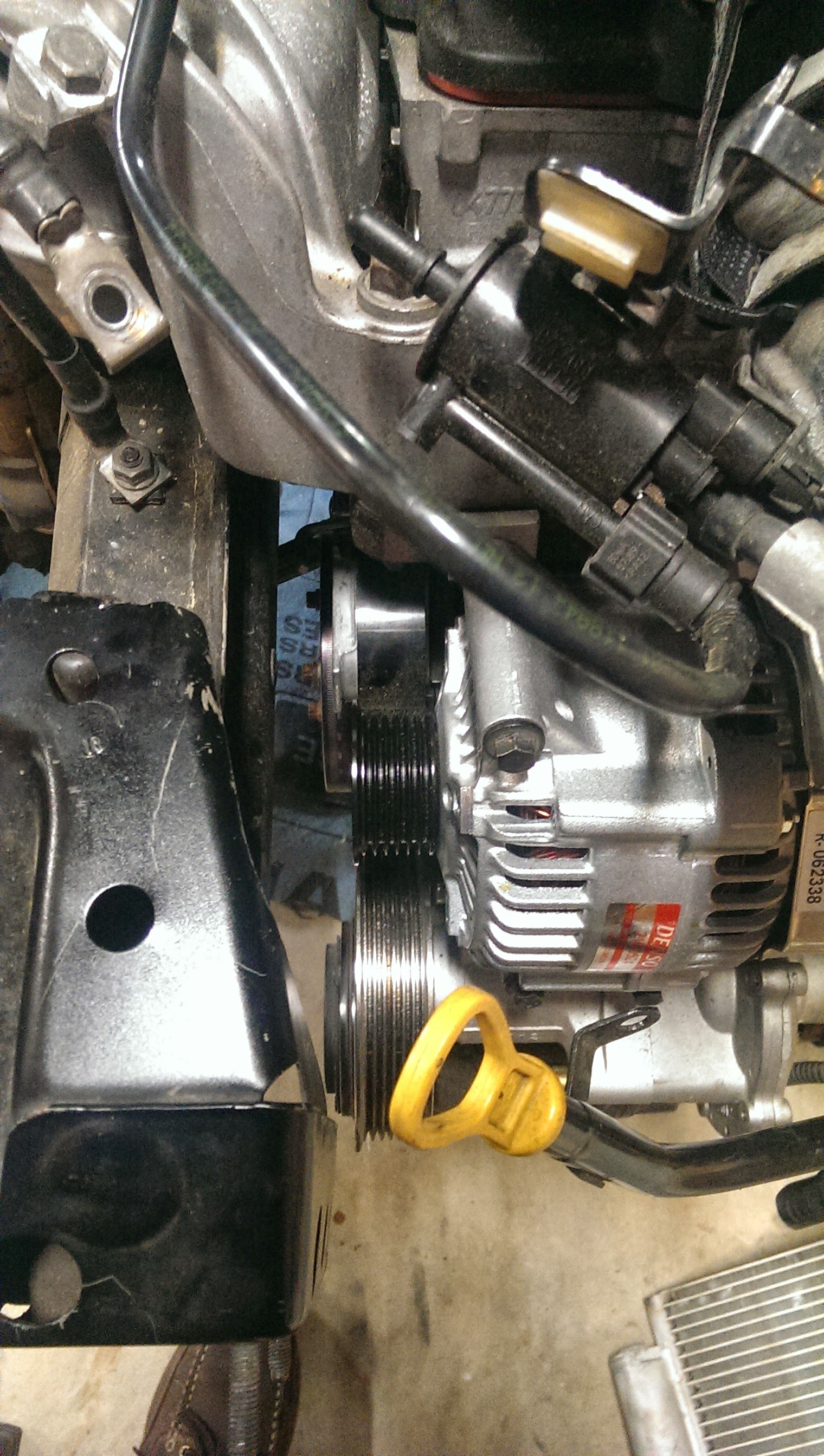
Okay, so, I finally worked out my alternator woes.
And I didnt have to convert to a 2 wire from the Denso 3! so that saved a hassle.
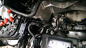
many of you will recognise this (it is a stock R53 alternator)
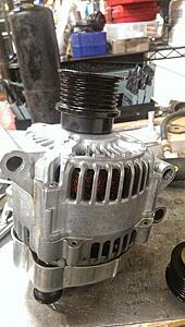
Well, when you try and put it where the stock cooper one goes because you took the supercharger off of the car, you begin to notice that the mounts on the engine are shifted to the left and upside down in pattern.
well crap.
Flip the alternator and now it "bolts on", but the top wont go down to the block!
So cut some shims for the bolt holes and now everything bolts up nicely,
Except crap!
those mounts being farther left stuck the pulley WAY past the other ones.
So I ended up stumbling upon some photos of mini ones that have our alternator, but had a much shorter pulley.
Long story short, ordered the pulley from Mini out of Germany,
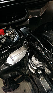
And here is the difference!
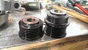
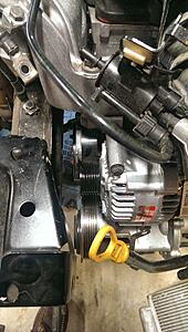
belt runs just a tad closer to that housing now eh?
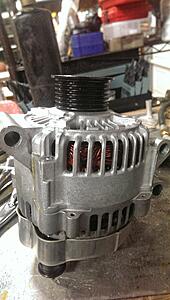
but at least it all seems to line up. Will not know for sure till I crank it for the first time.
And I didnt have to convert to a 2 wire from the Denso 3! so that saved a hassle.
many of you will recognise this (it is a stock R53 alternator)

Well, when you try and put it where the stock cooper one goes because you took the supercharger off of the car, you begin to notice that the mounts on the engine are shifted to the left and upside down in pattern.
well crap.
Flip the alternator and now it "bolts on", but the top wont go down to the block!
So cut some shims for the bolt holes and now everything bolts up nicely,
Except crap!
those mounts being farther left stuck the pulley WAY past the other ones.
So I ended up stumbling upon some photos of mini ones that have our alternator, but had a much shorter pulley.
Long story short, ordered the pulley from Mini out of Germany,
And here is the difference!

belt runs just a tad closer to that housing now eh?

but at least it all seems to line up. Will not know for sure till I crank it for the first time.
#333
06-07-2014, 08:03 AM
#334
06-13-2014, 02:17 PM
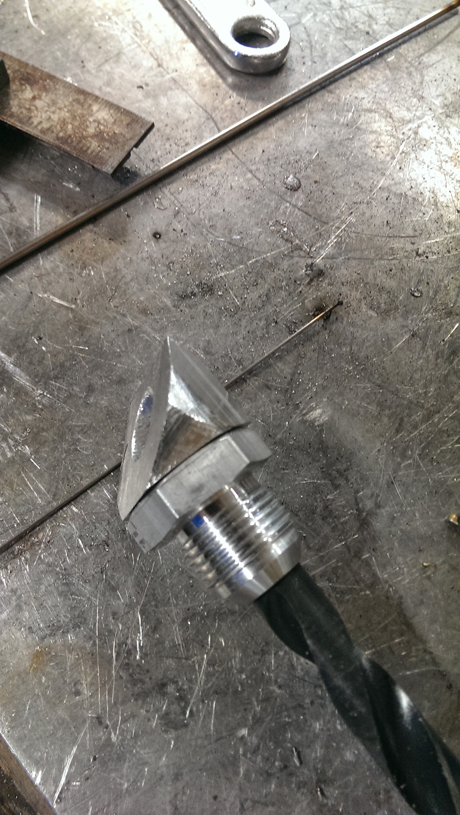
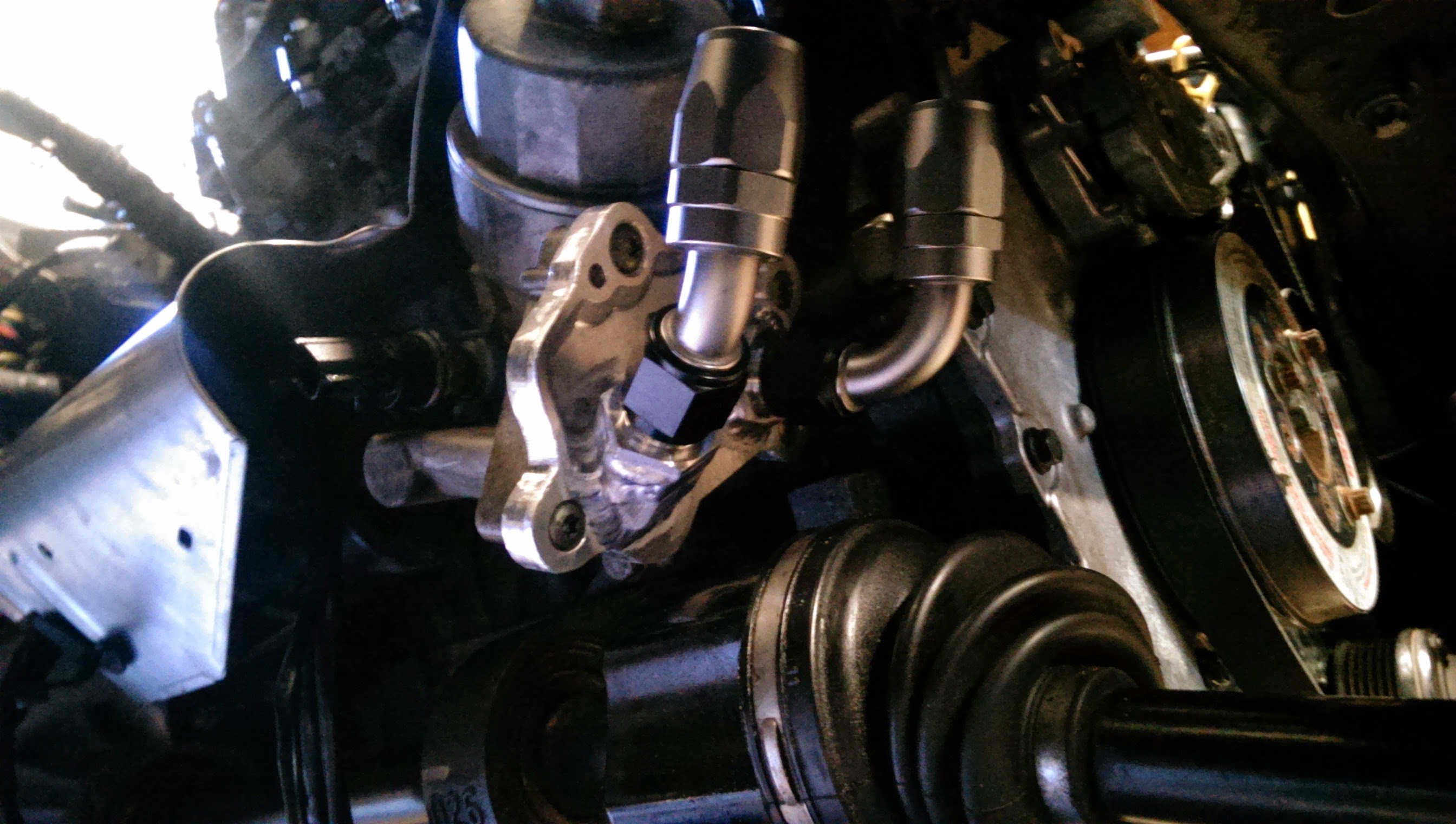
so, I made a snafu. oops.
Put the back port for the oil plate at the bottom of the oval instead of the top,
After I welded on the AN fittings and put the axle back in (didnt even think about this. kicked myself and was quite frustrated that I did not) , the hose fitting would not clear the axle

*sigh*
at least it looked pretty...

in other mess ups, I was welding some 1/4" thick aluminum for a small work related job (quicker for me to do it at home then submit a work order and have the shop do it)
I cracked one of my pyrex cups...
I guess thats what putting 180 amps out into aluminum with a glass cup gets you. sucker was HOT!
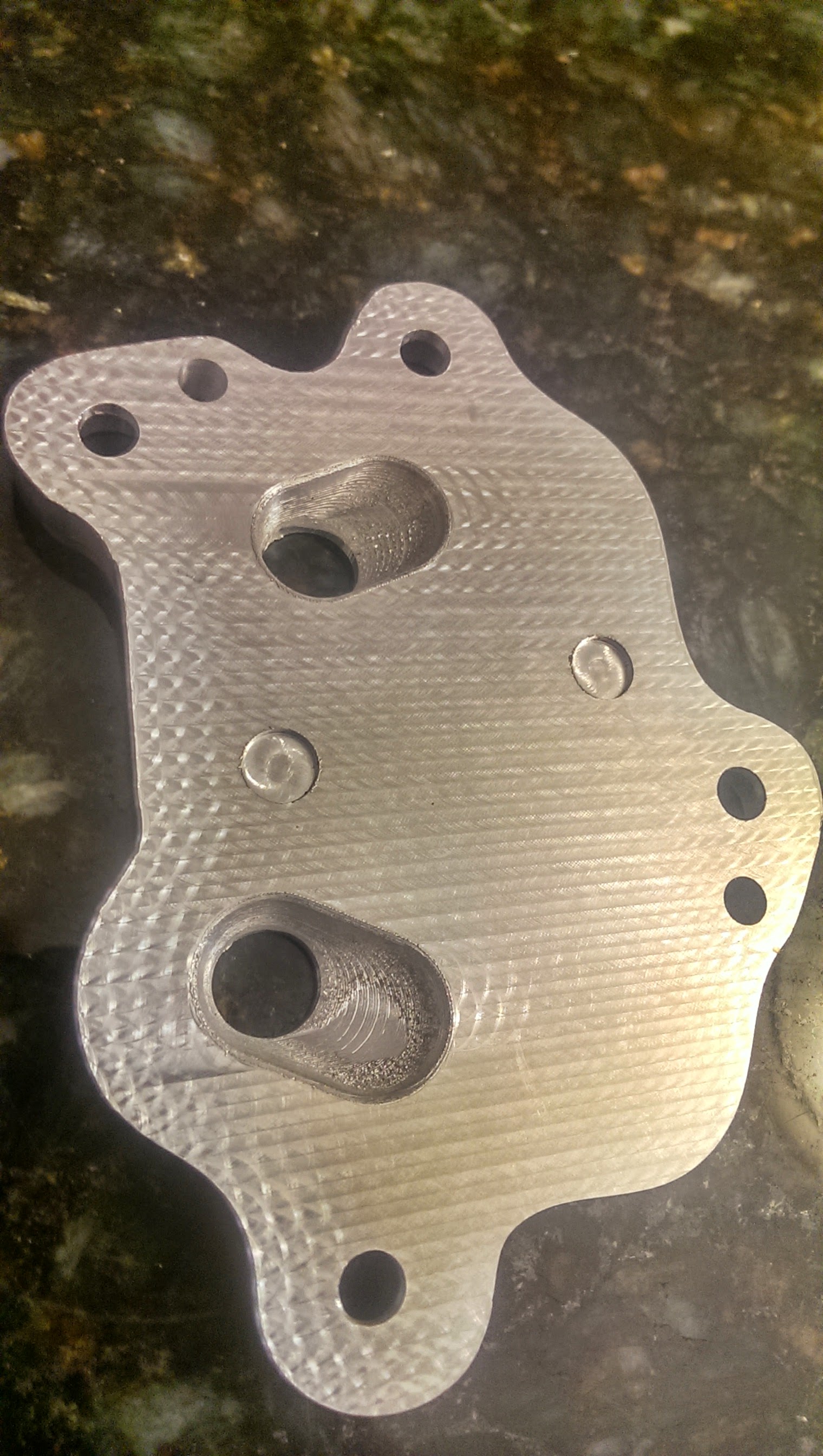
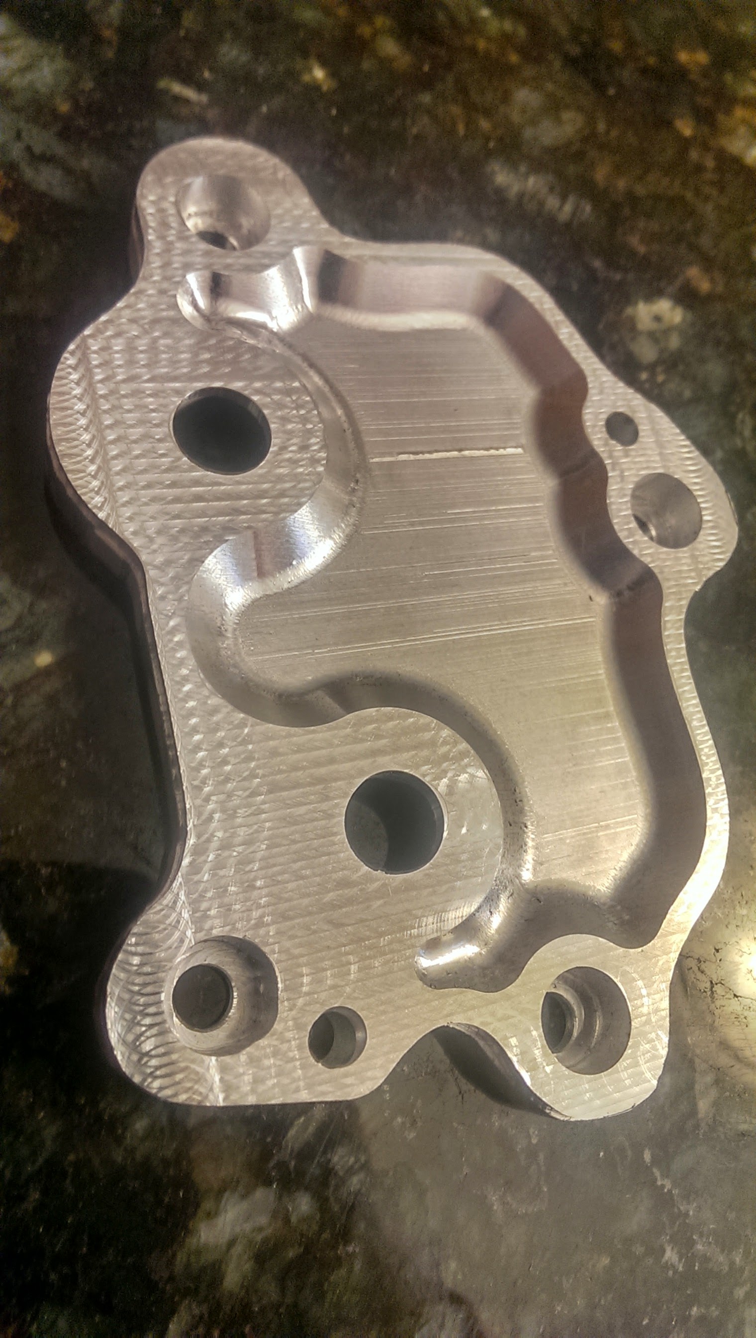
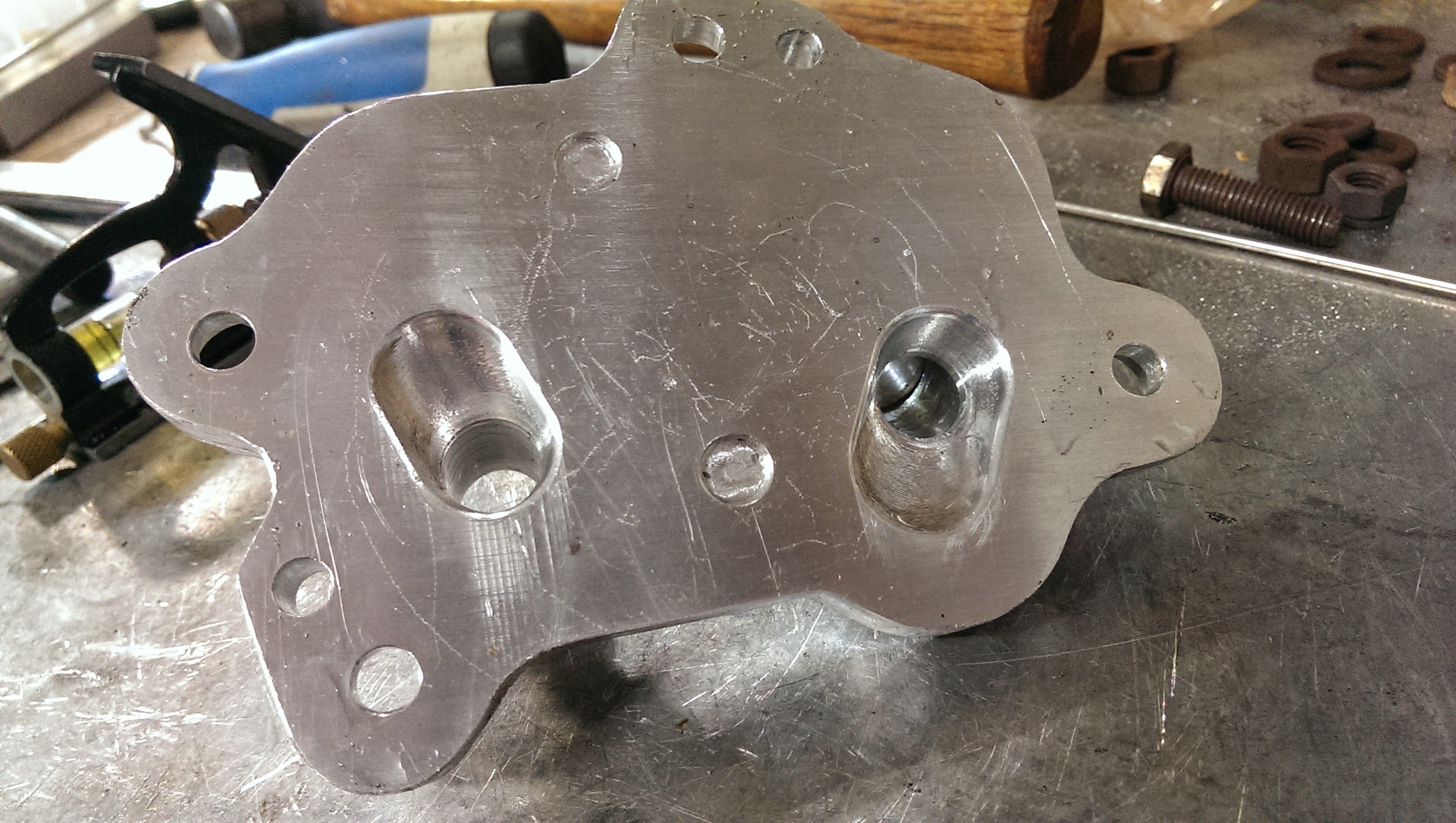
anywho, machined a new plate (port relocated up a little)

and then for good measure I took a hand lapping file and made it nice and smooth.
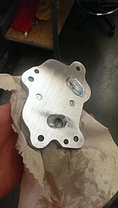
mmmm. smexy!
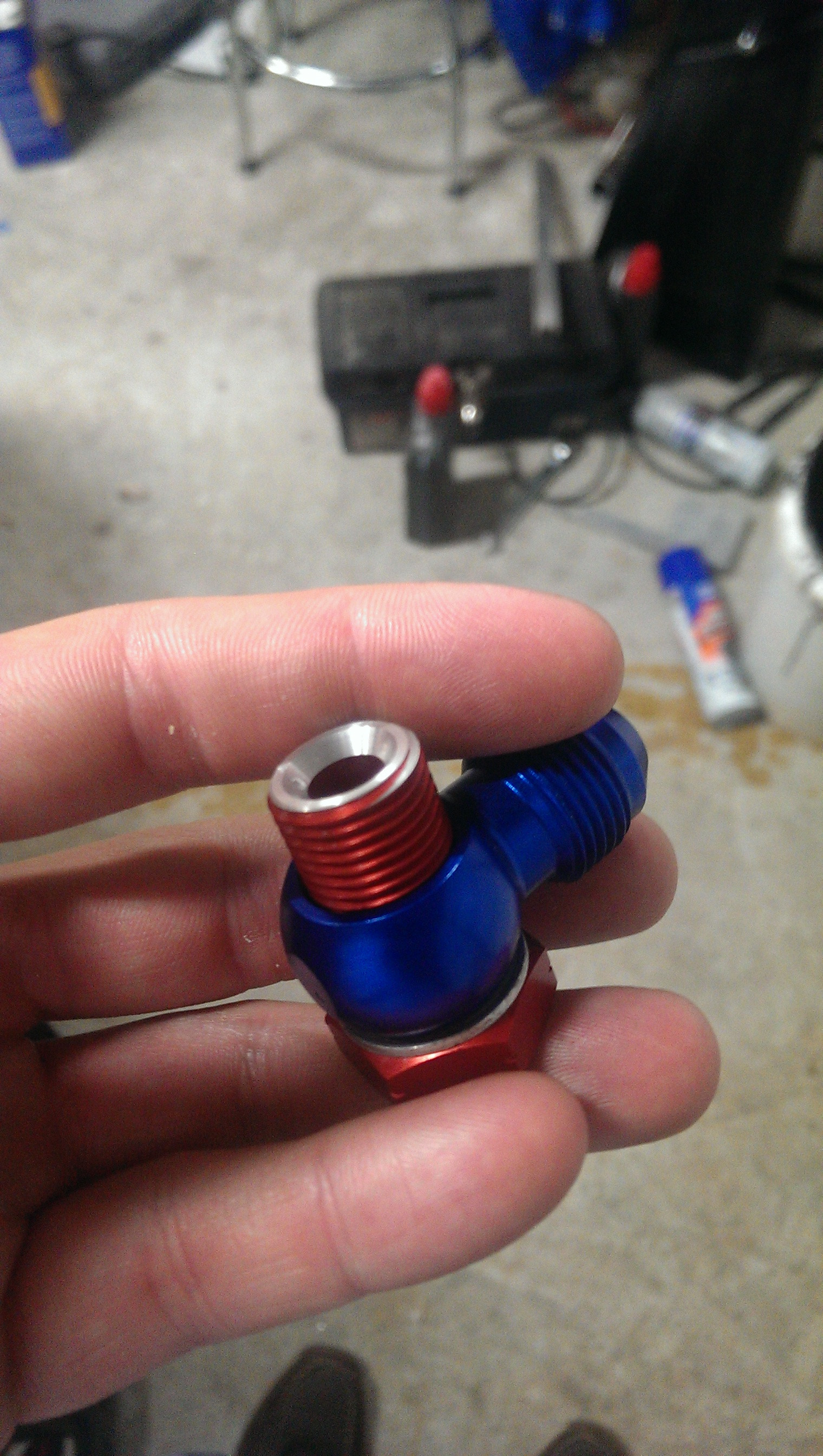
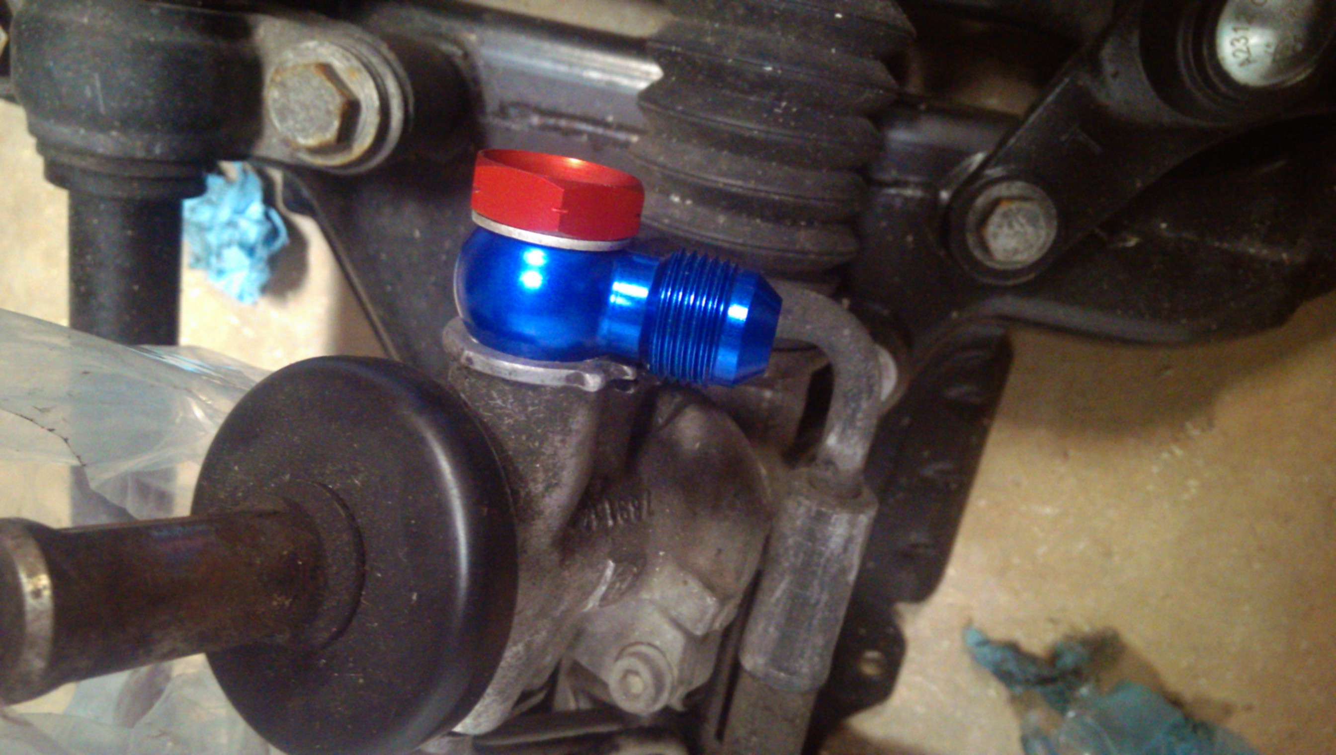
but while that was cutting, I also finished modifying the new fitting for the power steering relocate mod (will post pictures of this soon.. still working a few things out)
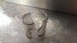
the red banjo bolt started at 32mm where the stock one was 28mm. The extra 4mm were not allowing the banjo to seat, so off some had to come!
Chucked it up in the lathe and turned it down, tapered the first thread, and then chased them back.
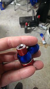
Threads in no issues!

now just to see if that tab on the PS neck causes any issues... if it does it shall meet my file. haha!
That is all for now. Super busy. Lots of stuff going on here.
but I will let slip that a
12"x3.5"x1.5" core from Bell intercoolers is on its way for me to weld up! (oil radiator)
Put the back port for the oil plate at the bottom of the oval instead of the top,
After I welded on the AN fittings and put the axle back in (didnt even think about this. kicked myself and was quite frustrated that I did not) , the hose fitting would not clear the axle
*sigh*
at least it looked pretty...
in other mess ups, I was welding some 1/4" thick aluminum for a small work related job (quicker for me to do it at home then submit a work order and have the shop do it)
I cracked one of my pyrex cups...
I guess thats what putting 180 amps out into aluminum with a glass cup gets you. sucker was HOT!
anywho, machined a new plate (port relocated up a little)
and then for good measure I took a hand lapping file and made it nice and smooth.

mmmm. smexy!

but while that was cutting, I also finished modifying the new fitting for the power steering relocate mod (will post pictures of this soon.. still working a few things out)
the red banjo bolt started at 32mm where the stock one was 28mm. The extra 4mm were not allowing the banjo to seat, so off some had to come!
Chucked it up in the lathe and turned it down, tapered the first thread, and then chased them back.
Threads in no issues!
now just to see if that tab on the PS neck causes any issues... if it does it shall meet my file. haha!
That is all for now. Super busy. Lots of stuff going on here.
but I will let slip that a
12"x3.5"x1.5" core from Bell intercoolers is on its way for me to weld up! (oil radiator)
#336
06-13-2014, 06:11 PM

5th Gear
#337
06-14-2014, 04:23 AM
#338
06-15-2014, 08:54 AM
but in all honestly I have been known to do it with a saw, hand files, and a hand die as well before. Usually I thread the die on "backwards, then cut the bolt, use a file to taper, debur as much of it as I can.
use a slightly modified 3 sided file to clean up the threads a hair, and then run the tap back down to chase the threads.
But onwards!

(to even more impressive things. I couldn't be happier at how this turned out)
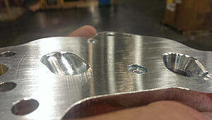
Okay, so those plates (the one that I messed up by putting the fitting too low so it wouldnt clear the axle)
Well I made another, As you have seen, And here it is!
(compared to the old one on top)

now, to be doubly sure as I am probably getting some upgraded axles (something tells me I will need them
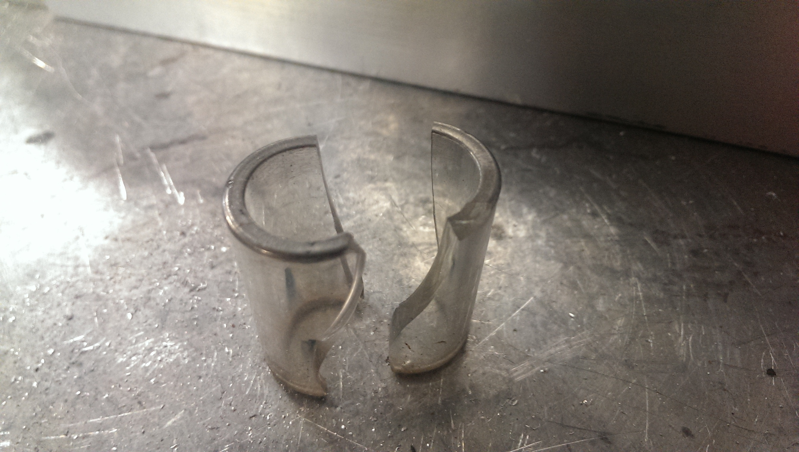
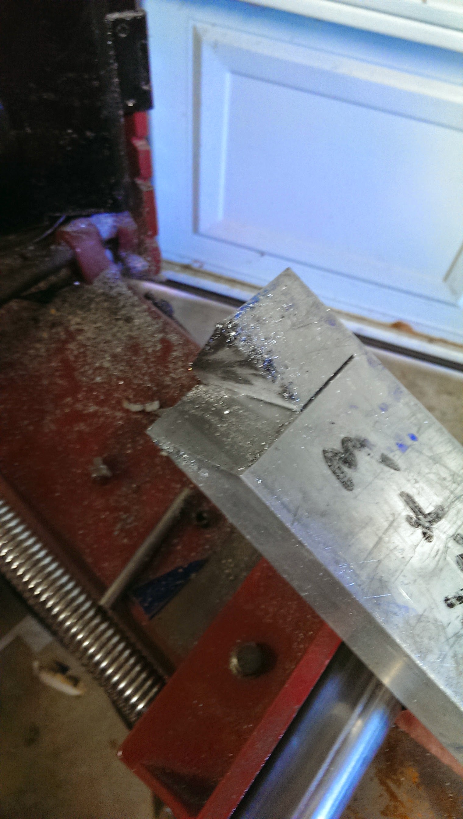
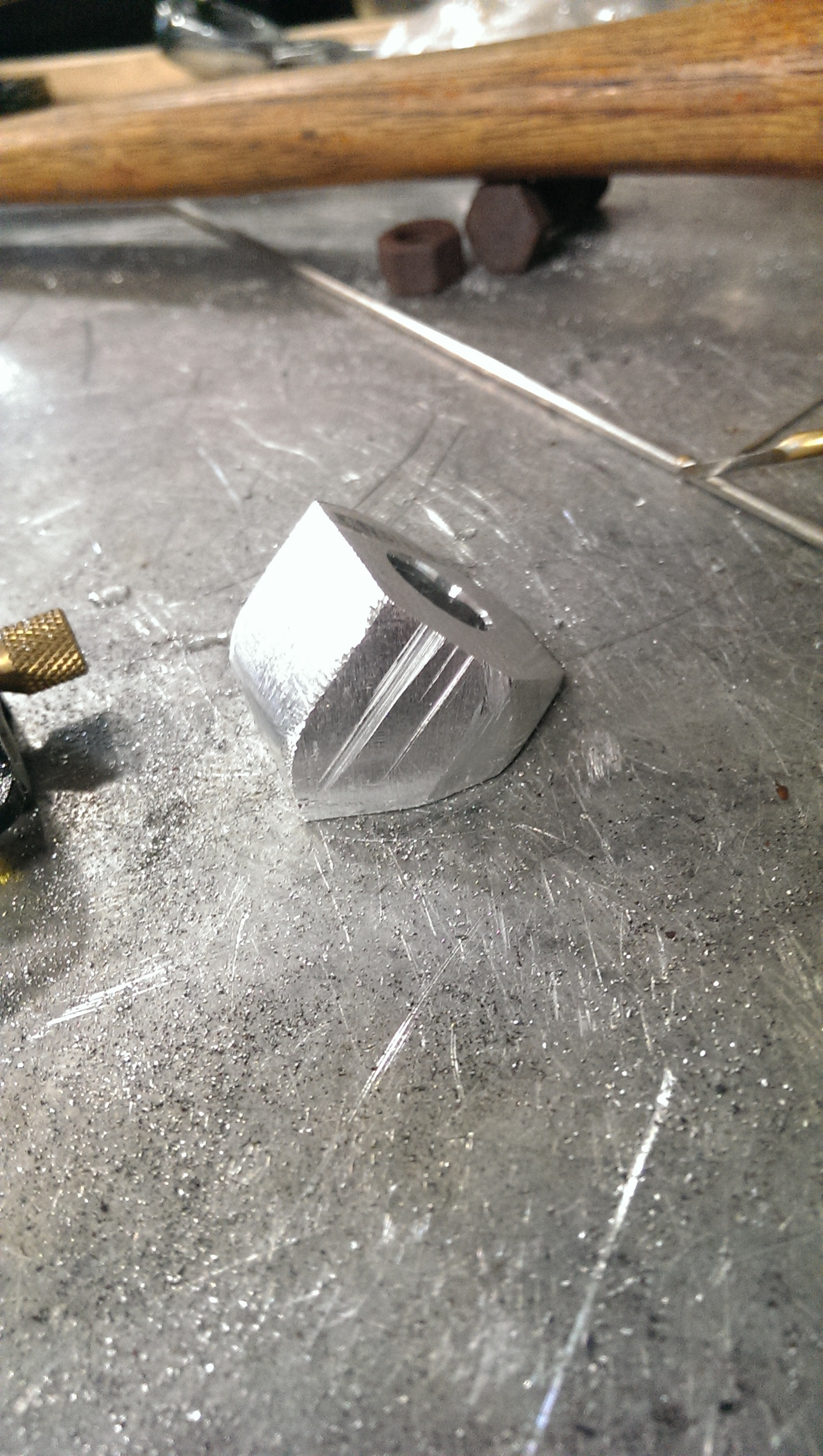
) and those Joints may get a little larger, I decided it best to also add in a 45� adapter. problem is its the weekend, I dont want to draw one up and go into work, and I cannot buy one anywhere.So old-school-cool time it is

This took a while (but not as long as I thought it would. Love these new starrett blades!
 )
)
cut the 45 above, then cut out the width of the piece I needed
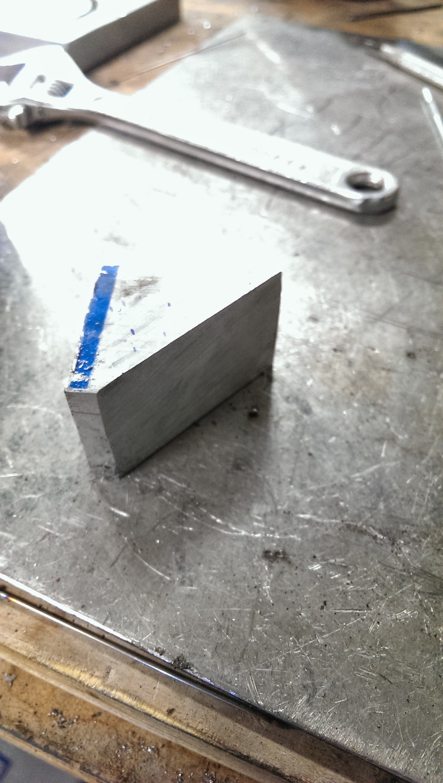
next I clamped it in a vice, lined up the AN fitting, marked the center of the hole, punched it with a centering punch, then used 8 drill bits to step up the size of the hole but keep it centered and smooth!
Next I blued the piece (using machining dye / blue) marked the "hex" profile of the outside of the AN weld fitting and cut the profile into the piece on the band saw.
Gave it a little clearance on the cutting, then I went back in and hand filed the sides down and tapered the back edge. Used a smooth cut file to finish things off
Came out nicely

Lined it up using the drill bit (and a piece of welding wire to help things out
)
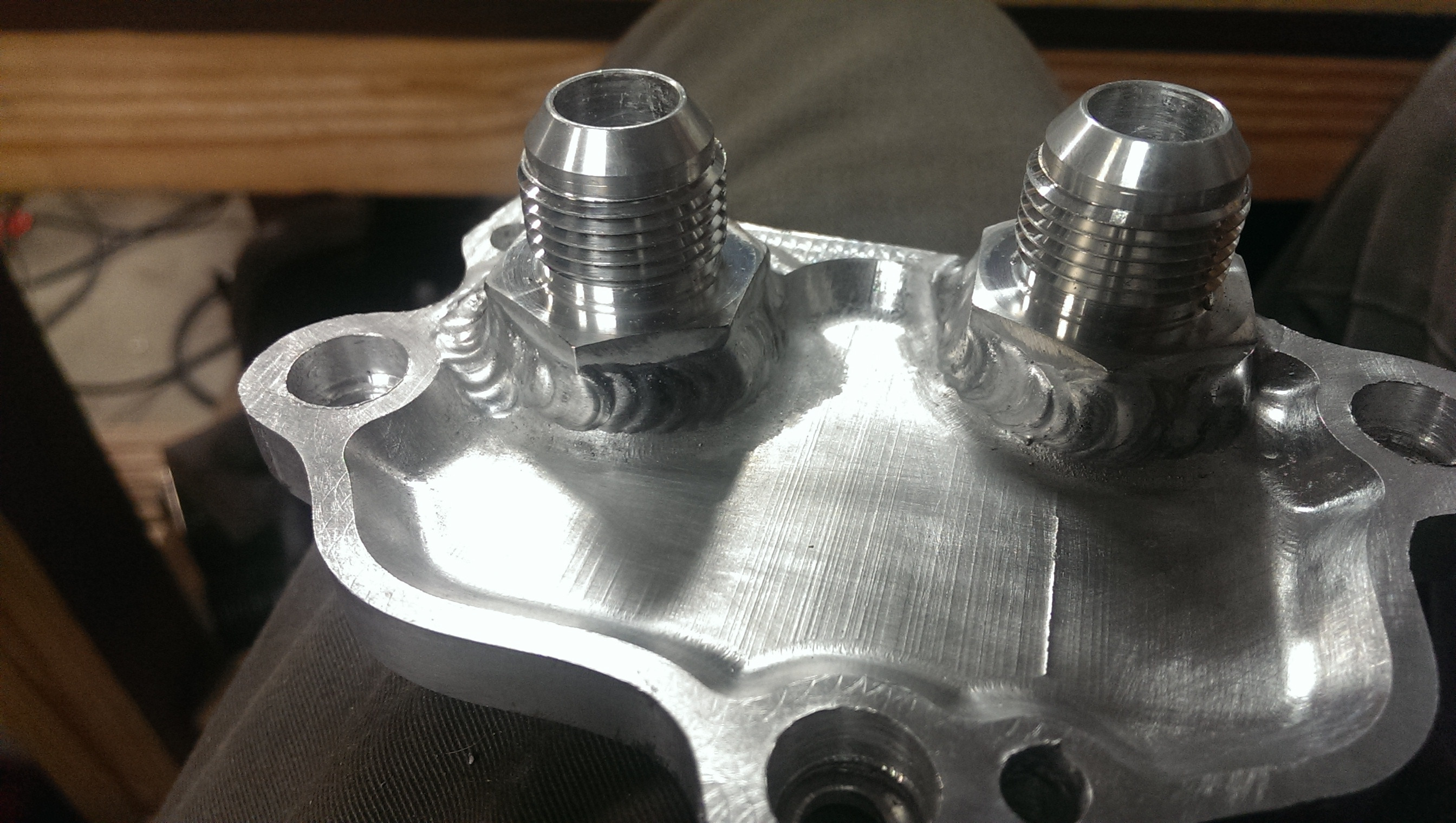
welded those two together, and then welded them to the plate!
Only needed to do the fitting with clearance problems, the other I welded on as before

back side (lemme tell you, my new torch cups that have narrow outlets on them were a life saver when doing that deep angle weld !
 )
)
and the back back side
holes line up nicely
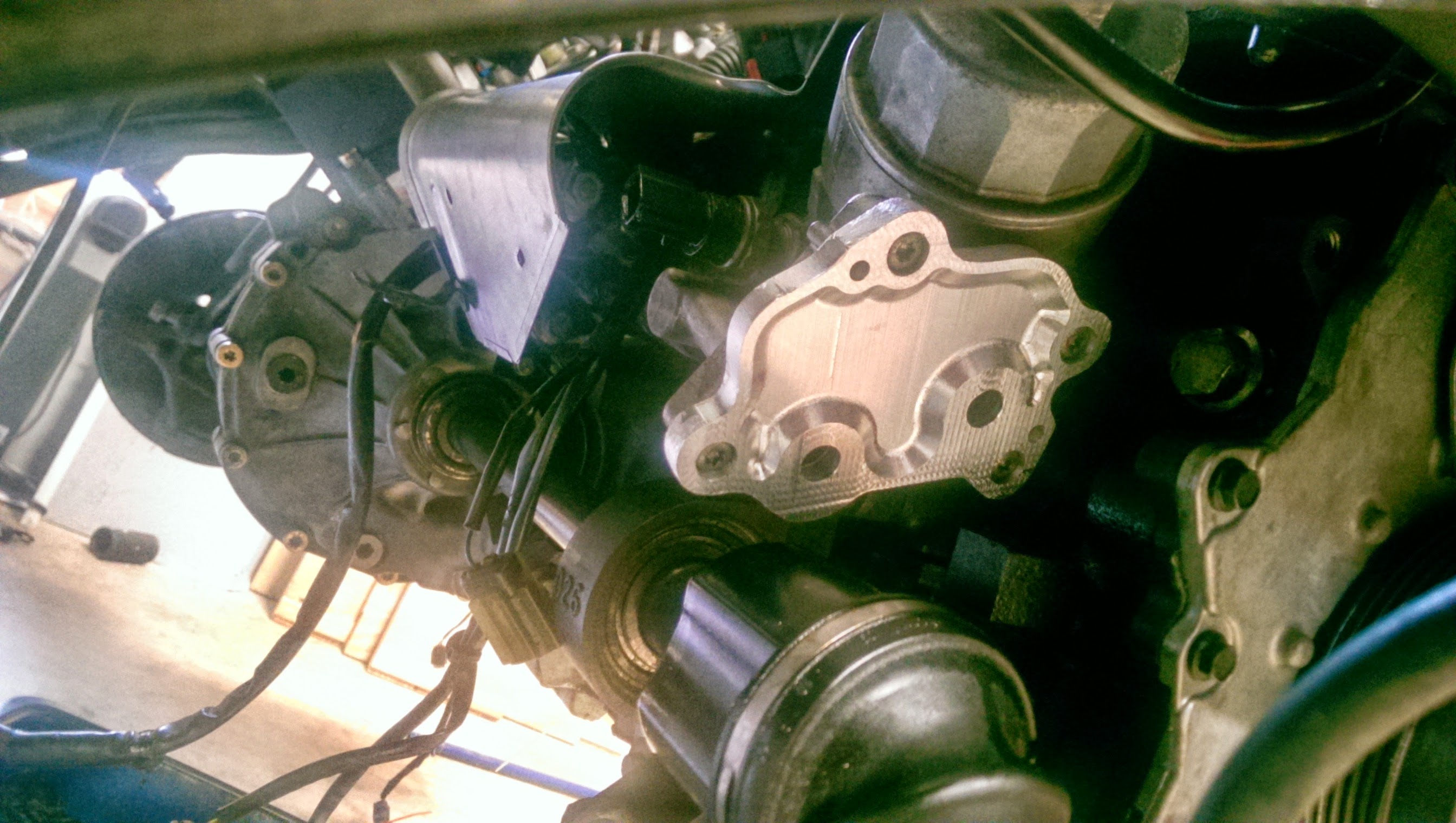
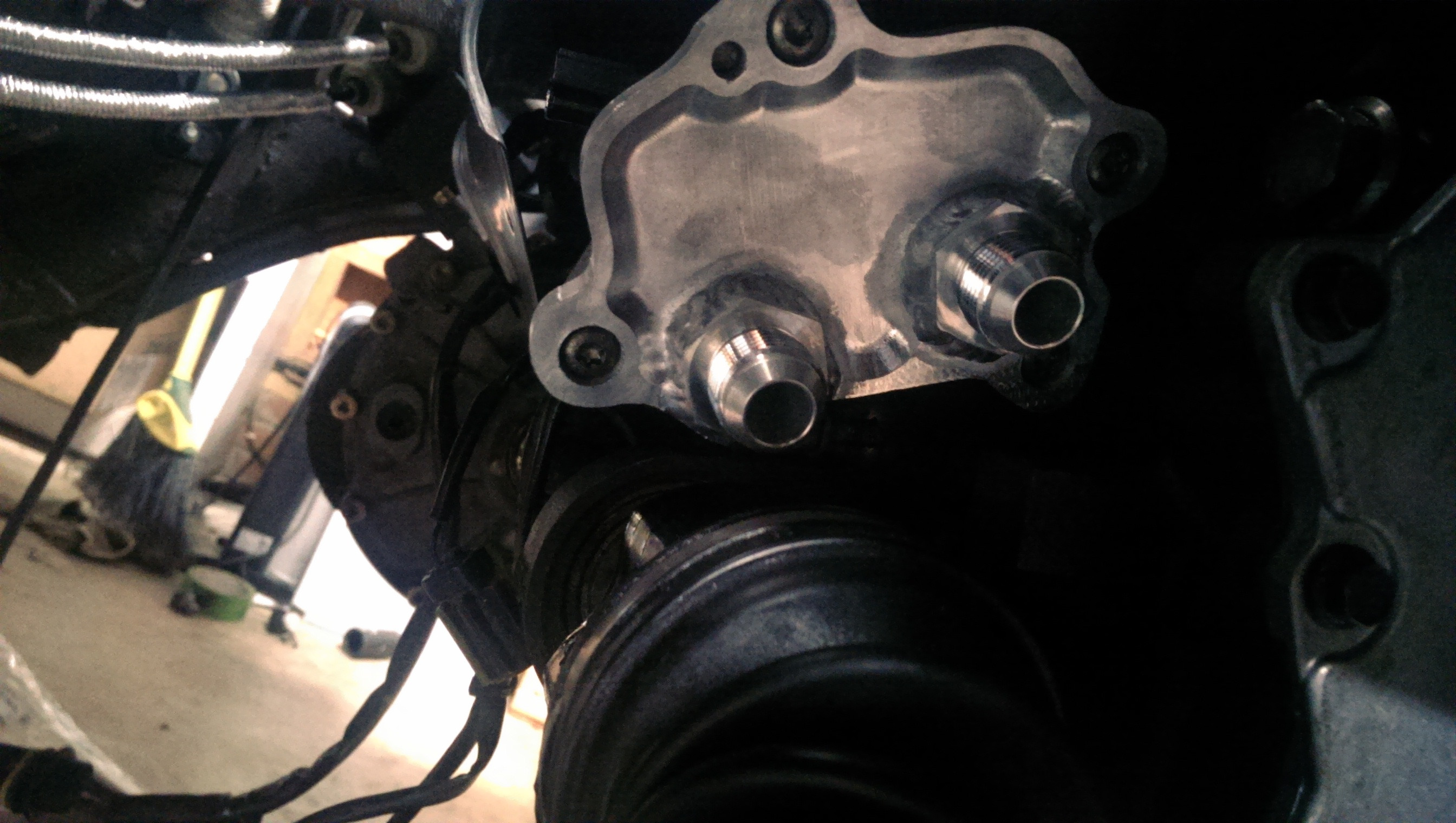
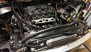
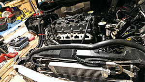
in the car
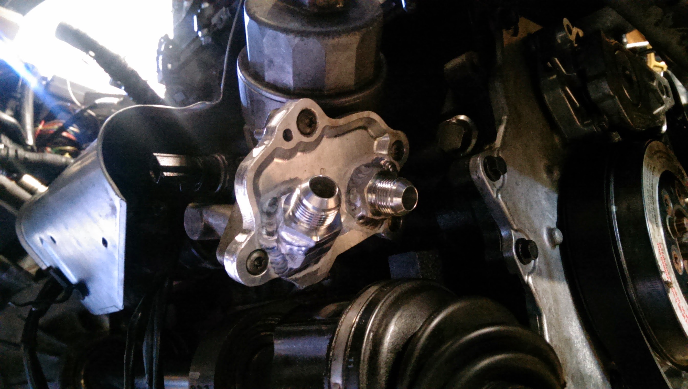
and with fittings test fit on!
Shouldnt have any problems with oil flow restrictions with this setup I dont think
Largest any of the other aftermarket ones are that I know of are -8AN (1/2" OD tubing) where as these are ~1/2" ID (5/8" OD)
#341
06-17-2014, 08:23 PM
I have this feeling as though every time I make a decent post in this thread it is almost like giving this sub forum a little bit of a shock from a defibrillator. Heart beats for a few seconds before it starts to flat-line again.
Oh well,
This time I turned it up to 11! (jk.. about a 7.. ish... the 11 should come in next week  )
)
anywho.
"making of an oil cooler"
So I was going to order an Earls oil cooler for my little project, but after in fact ordering one, they said it would not ship out till the end of NEXT month.
no bueno I said.
So, I decided instead (after a little more fruitless searching) to just make my own!
But no one really sells oil cooler cores.
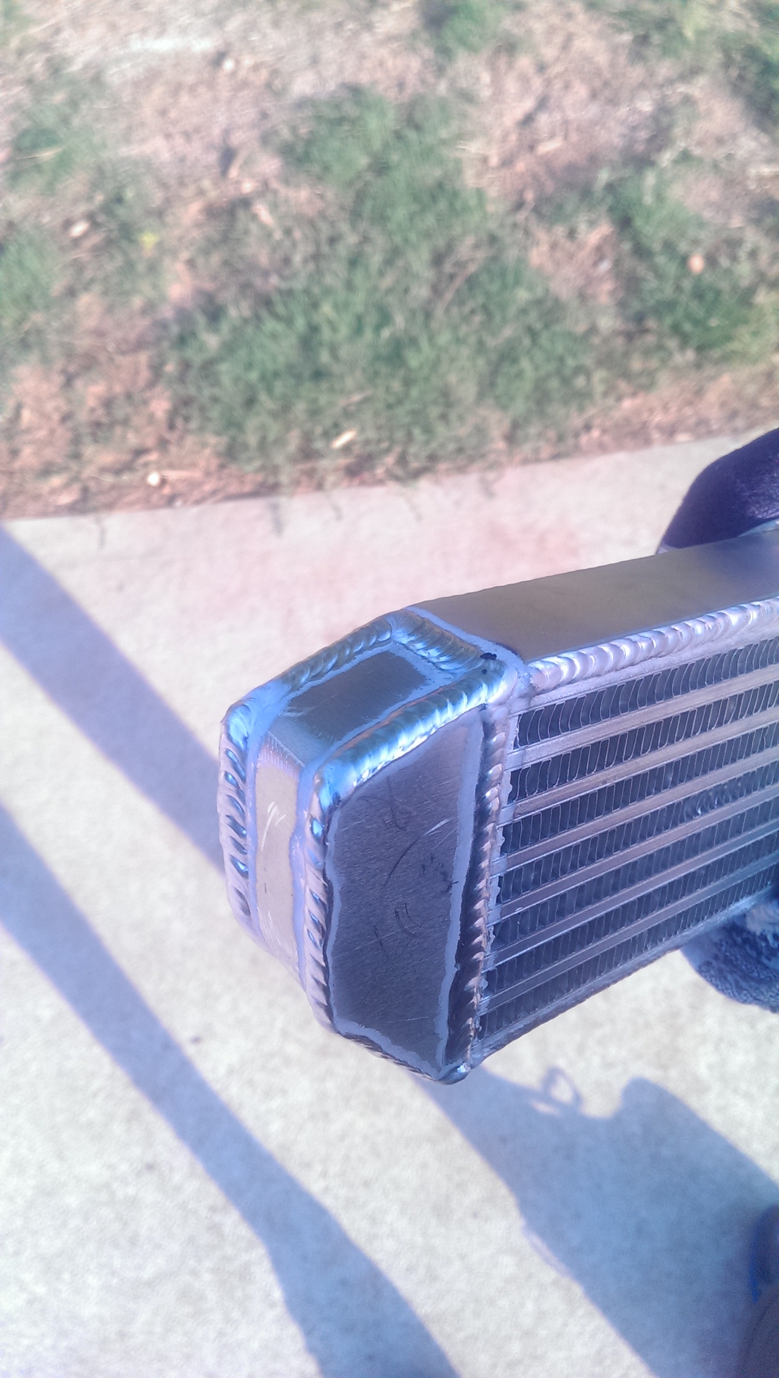
But they are close enough to a water core, so I decided just to start off with a core from Bell Intercoolers.
Measures 1.25" thick, 3.3" tall and 12.5" long. 100% 3003 aluminum construction and some nice beefy weld points.
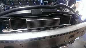
Idea here is to have it fed with a straight or 45 fitting on one side, and then have a 180 on the outlet for the return line.
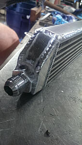
Return end tank (minus AN - 10 fitting)

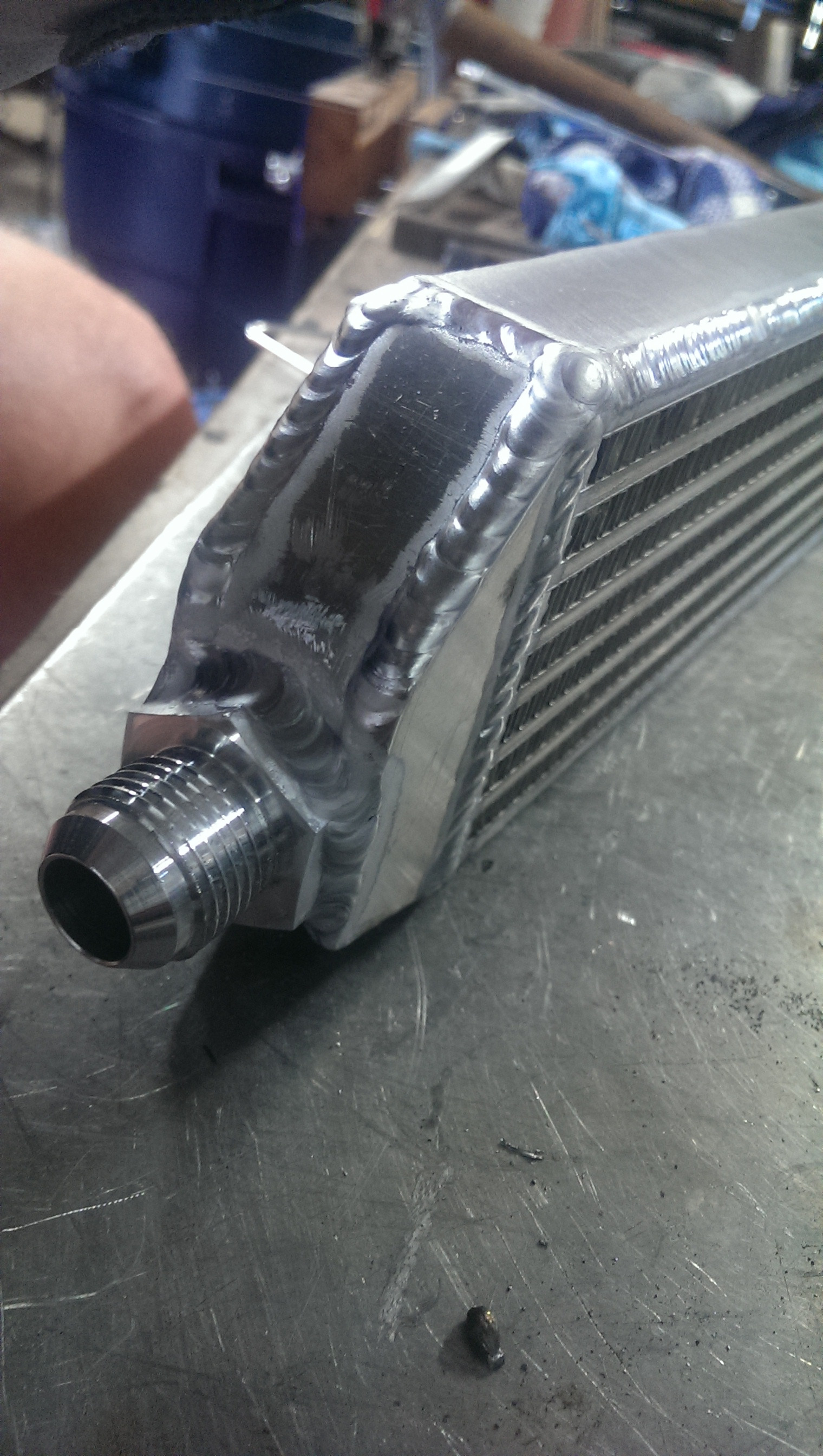
As usual I am using 6061 plate with a 4043 filler with a 100% argon shied. Using 3/32 filler rod (the 4043) and a 3/32 2% lanth tungsten on the torch with a gas lens and a #6 cup.
-10 fitting welded on (for the return side)
Another shot (from the other side)
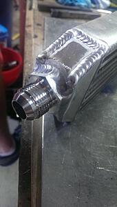
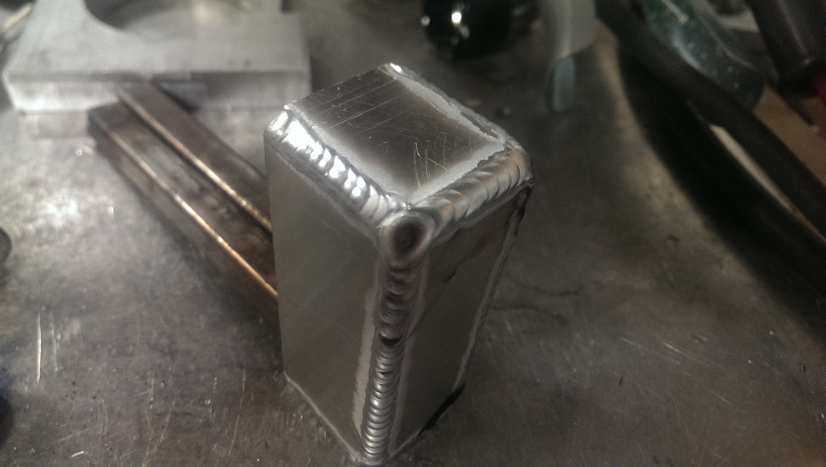
the infeed end tank
I made this one square as I want the flexibility to add in a temperature sensor, pressure sensor, or an auxiliary bleed / fill point to the oil system. Square profile just gave the most flexibility.
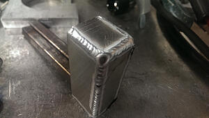
An fitting on infeed welded on and mock up
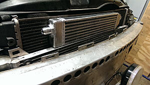
top shot of the mounting brackets (uses factory mount points)
And that is all for today!
Hope you enjoyed!
Oh well,
This time I turned it up to 11! (jk.. about a 7.. ish... the 11 should come in next week
)anywho.
"making of an oil cooler"
So I was going to order an Earls oil cooler for my little project, but after in fact ordering one, they said it would not ship out till the end of NEXT month.
no bueno I said.
So, I decided instead (after a little more fruitless searching) to just make my own!
But no one really sells oil cooler cores.
But they are close enough to a water core, so I decided just to start off with a core from Bell Intercoolers.
Measures 1.25" thick, 3.3" tall and 12.5" long. 100% 3003 aluminum construction and some nice beefy weld points.

Idea here is to have it fed with a straight or 45 fitting on one side, and then have a 180 on the outlet for the return line.
Return end tank (minus AN - 10 fitting
)
As usual I am using 6061 plate with a 4043 filler with a 100% argon shied. Using 3/32 filler rod (the 4043) and a 3/32 2% lanth tungsten on the torch with a gas lens and a #6 cup.
-10 fitting welded on (for the return side)

Another shot (from the other side)
the infeed end tank
I made this one square as I want the flexibility to add in a temperature sensor, pressure sensor, or an auxiliary bleed / fill point to the oil system. Square profile just gave the most flexibility.
An fitting on infeed welded on and mock up

top shot of the mounting brackets (uses factory mount points)

And that is all for today!
Hope you enjoyed!

#344
06-18-2014, 05:07 AM
I think that most of us (well, maybe, make that some of us, er, uh, OK, I) look forward to this - I've made an icon on my desktop that takes me directly to the page. But some of us, (er, uh, I) still look for new postings like we used to run to the mailbox looking for this month's Playboy. And most of us don't want to appear more stupider than we have already appeared by asking dumb questions. And, to use the Playboy analogy again, most of us will never see something like this in the flesh.
But I do have to point out that I contributed the obviously valuable idea of making the oil heat exchanger (see #325). Its good to see that my contribution was appreciated. You would never have thought of making your own had I not suggested it. Us old guys still rule. At least we still run to the mail box. And I never just look at the pictures.
But I do have to point out that I contributed the obviously valuable idea of making the oil heat exchanger (see #325). Its good to see that my contribution was appreciated. You would never have thought of making your own had I not suggested it. Us old guys still rule. At least we still run to the mail box. And I never just look at the pictures.
#345
06-18-2014, 05:09 AM


#347
06-18-2014, 01:49 PM
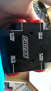
so, quick question.
I can always prime the system and just see which way the oil flows, but does anyone know which port on the oil sending plate would the the "outlet port"?
I can get the car running without an oil thermostat, but I need to know flow path before I can add one in for day to day reliability without having to worry about the oil being *too* cold.
#348
06-20-2014, 07:49 PM
well, apparently no one knows off the top of their head.
As well as no one seems to be running an oil thermostat on stand alone oil cooling systems :/ .
To me it seems like a good idea haha, so I did it anywho.
from earl's (holley)
Anywho, started with the mount for the thermostat.
Rough cut two pieces of aluminum, bent one of them, blued them up, marked them with a scratch awl
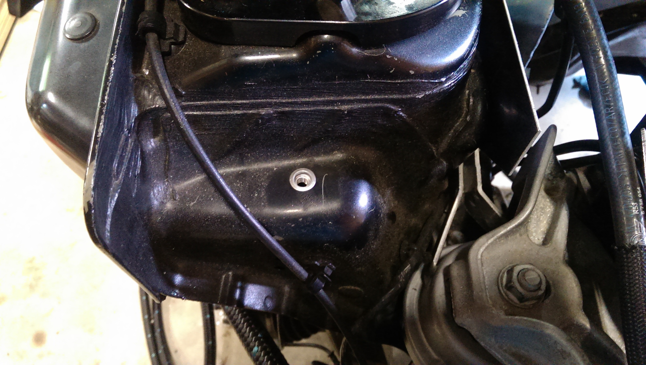
put a riv nut into that random hole in the factory sheet metal

then I finish cut, filed, deburred, removed the blue, clamped the two pieces together and welded them up
Next I drilled two holes and put riv nuts in those to mount the thermostat.
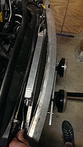
then I trimmed two areas in the front radiator surround to pass cables through.
These were cut so that I could unbolt the radiator and swing the whole mess out of the way without disconnecting any cables.
Will probably be printing a piece to fill that hole in the return line (the one with the 180 � AN fitting
And then I set about cutting and assembling all of the AN lines.
I did some checking and the thermostat should work both ways in reality.
but in either case it will not starve the motor of oil.
I can at least crank it, get everything wet, shut it off, disconnect a line and then re-crank it briefly and see which line starts gushing.
Trimmed both AN lines to have some slack so they can be moved as needed.
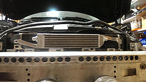
Another shot of the front
Very glad I didnt go any larger. This is probably the largest radiator I could have ever hoped to fit. (clearances are less than 1/8" at a few points when the hood comes down. )
Hope you enjoyed!
As well as no one seems to be running an oil thermostat on stand alone oil cooling systems :/ .
To me it seems like a good idea haha, so I did it anywho.
from earl's (holley)

Anywho, started with the mount for the thermostat.
Rough cut two pieces of aluminum, bent one of them, blued them up, marked them with a scratch awl

put a riv nut into that random hole in the factory sheet metal
then I finish cut, filed, deburred, removed the blue, clamped the two pieces together and welded them up

Next I drilled two holes and put riv nuts in those to mount the thermostat.

then I trimmed two areas in the front radiator surround to pass cables through.
These were cut so that I could unbolt the radiator and swing the whole mess out of the way without disconnecting any cables.

Will probably be printing a piece to fill that hole in the return line (the one with the 180 � AN fitting
And then I set about cutting and assembling all of the AN lines.
I did some checking and the thermostat should work both ways in reality.
but in either case it will not starve the motor of oil.
I can at least crank it, get everything wet, shut it off, disconnect a line and then re-crank it briefly and see which line starts gushing.
Trimmed both AN lines to have some slack so they can be moved as needed.

Another shot of the front
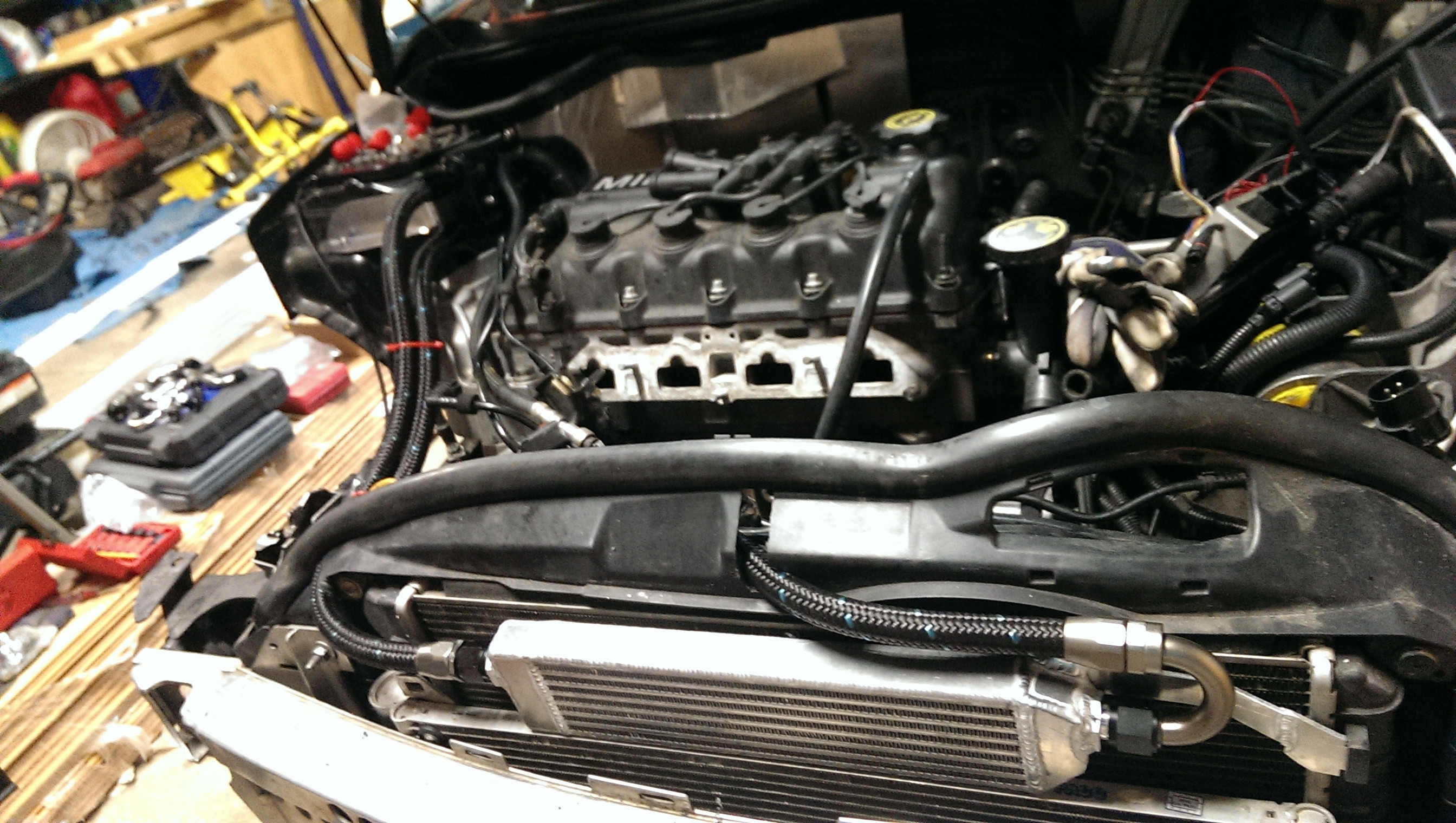
Very glad I didnt go any larger. This is probably the largest radiator I could have ever hoped to fit. (clearances are less than 1/8" at a few points when the hood comes down. )
Hope you enjoyed!

#350
06-20-2014, 08:32 PM
exhaust parts back from swaintech monday.
Intercooler pieces should be done monday as well. (ugh. tired of delays with those, but they guy is throwing me a bone and doing them at cost in his free time, so for the price it is hard to complain)
Axles ship monday, and should be here thursday.
Then I just have to worry about plumbing and double checking torques on a lot of bolts to make sure everything is buttoned up.
Then I can at least attempt to crank her and work on some ECU tuning.