When you click on links to various merchants on this site and make a purchase, this can result in this site earning a commission. Affiliate programs and affiliations include, but are not limited to, the eBay Partner Network.
great job Tigger2011, looking forward to wrapping trim pieces this weekend
I just bought some 3m 1080 film ... keep up the great work
JJ Pembroke pines
So we all know that even with catch cans installed some amount of oil will find it's way into the intake charge. My current setup consists of a single in / dual out RX catch can. The passengers side port it plugged and the drivers side empties into the catch can. One side of the catch can goes to the intake manifold and has a one way UPR check valve to prevent boost from pressurizing the catch can. The other side of the catch can goes to the inlet venturi before the turbo and also contains an inline UPR check valve to prevent air being sucked through the catch can and into the intake manifold when not in boost. The system works extremely well but oil vapor still condenses in the lines overnight. With the Phormula knock sensor installed I've noted occasional minor detonation but only on the first pull of the day. Once any residual oil is out of the system Vlad runs like a champ so I decided to investigate alternative solutions. The first idea was to utilize the Vibrant Performance exhaust evac venturi. We use a similar system on aircraft by placing venturies that protrude out of the wing or fuselage into the air stream. These work very well at the speed an aircraft travels, but how well will they work in an exhaust system remains to be seen. The first step was to measure the effectiveness of my current system so I first purchased a new oil cap and modified my old cap by adding a pneumatic tap.
This was plumbed to a digital manometer to measure the amount of vacuum or pressure inside the crankcase.
What I discovered is that when not in boost the crankcase is under a varying level of vacuum which is regulated by the valve cover. Once the engine is warm and at idle the vacuum averages -0.80 to -0.85 inches of mercury even though the manifold vacuum is approx. -20 inHg. During normal driving the amount of vacuum stays at approximately -1.0 inHg but will increase to as high as -1.30 inHg during sudden throttle closure. This is transitory in nature and is quickly reduced to the -1.0 previously noted. This prevents over-scavenging which could result in oil being pulled out of the engine.
I also discovered than when in boost the intake venturi simply cannot provide the vacuum necessary to keep Vlad's crankcase under negative pressure. At 25 lbs of boost crankcase pressures climbed as high a 3.30 inHg or approximately 1.6 psi. This level of pressure has not resulted in blown gaskets, oil leaks or similar problems. In fact I was completely unaware it was occurring at all. Nonetheless I am certain it is resulting in some amount of lost power due to ring float.
The next step was to purchase the Vibrant exhaust evac system and modify an AN10 cap in a similar fashion to the oil cap.
You will note that I have placed a black mark on the venturi to make it easier to identify the orientation of the venturi once installed in the exhaust. The installation instruction show the venturi mounted like this.
This is rotated approximately 180 from the orientation used in aircraft. Marking the venturi allowed me to test it in both positions to see if one produced more vacuum than the other. Vlad's exhaust is 3" as previously noted and includes a Magnaflow muffler and OBX resonator both of which are straight through designs. For testing purposes and to reduce back pressure to the minimum I removed the resonator and installed a straight pipe with the bung for the venturi.
During testing the Vibrant Evac system never produced more than -0.05 inHg and under full throttle and boost produced a positive pressure of 0.05 inHg. Needless to say the system produced far less vacuum than hoped for and would be unsuitable for our purposes. I have some other ideas utilizing a ring venturi but in the mean time the Vibrant venturi has been removed and the port capped.
In summary while the Vibrant Evac system might be workable in a larger displacement engine running straight pipes, it is pretty well useless in our application. Oh well. Until next time... Happy Motoring.
What effect would capping the PCV tube going to the turbo and running the PCV port from the valve cover to the venturi on the exhaust have? You could put a check valve inline and it only vent while under boost. I have seen this on NA engines and it worked well. Crankcase pressure never got above atmospheric. This would also eliminate the catch can for that side.
What effect would capping the PCV tube going to the turbo and running the PCV port from the valve cover to the venturi on the exhaust have? You could put a check valve inline and it only vent while under boost. I have seen this on NA engines and it worked well. Crankcase pressure never got above atmospheric. This would also eliminate the catch can for that side.
That was the way I planned to route it but my goal is to also generate vacuum in the crankcase while in boost if I can. I may still test it that way but if I can keep the case negative the rings will stay seated and there should be less blow by. That means higher cylinder pressure, therefore more torque and HP. The amount of gain is directly related to how much vacuum you make, although anything over -15 inHg is considered too much as it can pull oil out of a wet sump oil system.
Your question also got me to thinking. Technically I can connect my catch can setup to either port. So now I'm curious to see if crankcase vacuum behavior differs through the passenger side port.
I finished designing a simple single stage venturi vacuum ring for installation in the exhaust. After calculating venturi area, flow rate and exhaust gas density it doesn't look like we can get much more than -.319 inHg without creating restriction in the exhaust. But what the hell, my math could be wrong so I'll give it a go.
If all else fails the backup plan is to use a Dorman 306-020 impeller air pump to generate vacuum. It would use a resistor to drop the voltage down to 9V for longevity of the pump for normal driving. At that voltage they generate approx -2.0 inHg. Then use a pressure switch and relay to provide 13.5V to the pump at 3 psi of boost and higher. These pumps when used for PCV evac systems on LS1's usually make -4.0 inHg at 12 volts so it "should" keep the case negative at all times. There's a lot of fiddly bits when going this route so I'm really hoping my math sucks and the venturi works.
Ok so the ring venturi was a bust. Not real surprised there. Have one final test to run before ordering the components for an electric evac system (Boost switch, relay, pump, etc.). Ordered the following for a little something I'm tinkering with...
I'll be installing the EBC boost controller over the weekend which will free up the pod currently housing my boost gauge.
Also planning to order the Maxton Design front splitter for the JCW. Out of the ones I could find that were JCW specific I think I like it the best.
Swapped out the wastegate for the IWG75 twin port from TurboSmart. Since the wastegate arm on the K04 is a different length I wanted to install it direct without the controller to verify wastegate cracking pressure.
I ordered one with 14 lb springs since you can basically double that boost wise with a single port controller. The idea being it would be fine to 28 psi on the single port. Once Vlad gets some upgraded internals the plan is us the extra port to go over that. As an FYI the wastegate cracking pressure in our application is 16.8 psi with the 14 lb springs. Next up will be wiring in the controller.
So far I'm absolutely loving the Cortex EBC. No more boost spikes as the turbo comes up to speed and I have full control over when, how and how much boost to run. Both ports are now connected to the boost solenoid which I temp installed while I make a bracket for it.
Thought I'd post some how-to info to help others that might be interested in running an EBC. The Cortex really only needs three connections other than power to function. Boost input via a port tap, throttle pedal input (TPI) and RPM input. To use the boost by gear function you also need a vehicle speed signal (VSS) input. Below are pin outs and diagrams I put together.
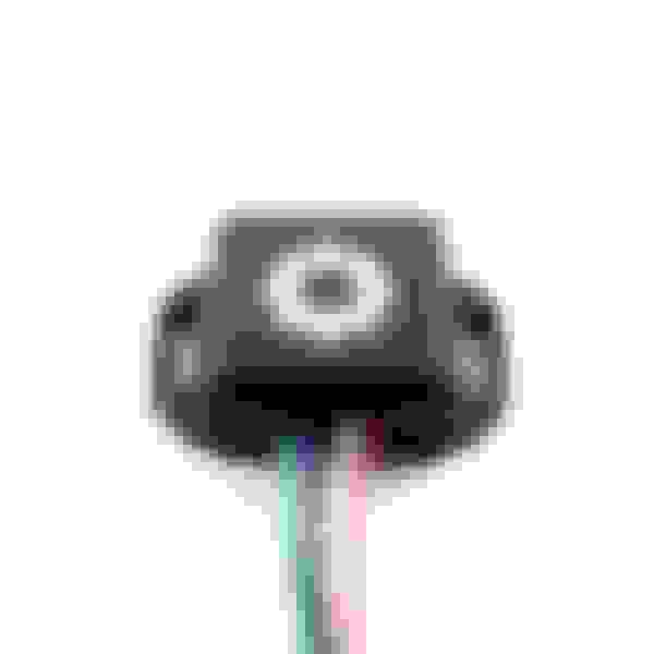
First up the ECU with connectors. We're only interested in the forward and aft connectors. I used posi-taps to tap the signal lines and feed the Cortex.
X60004 is where you pull the signal from the throttle pedal module
You can tap either pin 34 or 35. I tapped pin 34.
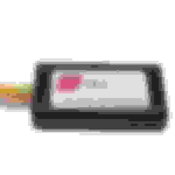
So now that the boost controller knows how far I have my foot into it ;-) it needs to know current RPM. For this signal I tapped into the ignition coil signal from the aft connector X60232.
You have four pins to choose from but it doesn't matter which one. I chose pin 10 which was the easiest for me to get to.
Since I already had a boost gauge I just put a T fitting to tap the silicone boost line to the Cortex. At this point I had a functioning boost controller but no boost by gear yet without a VSS input. The Cortex compares vehicle speed to RPM in order to know what gear your in. Cortex has several way to tap into a VSS signal so I chose the least expensive option which is a speed sensor adapter.
This takes input from a Hall effect or variable reluctance device and converts it into a signal the Cortex can read. Since we have Hall effect ABS sensors I thought this would be perfect and tap into ABS module connector. A little digging around convinced me this connector was not the way to go as BMW hung the ABS module in the air and built the car around it. Plan two involved tapping into the ABS sensor lines between the connector behind the left front wheel liner and the ABS module.
Unfortunately, the BMW wheel speed sensor operates at a much lower voltage than most other vehicles. Normally the pulsed signal is between .5 volts at rest and up to 1 volt as the teeth pass the sensor. Our sensors generate .34 mv at rest and approx. .500 mv at 45 MPH. So the speed sensor adapter was a bust. Luckily, they make a CAN-BUS adapter that connects to two wires of the OBD port that can take the OBD signals for RPM and VSS and convert them into a signal for the Cortex. So I ordered it and it should arrive this week. Right now I'm running with boost limited to 21 psi as a compromise till I can configure the boost by gear setting. Had I bought this first I could have passed on tapping the ECU coil signal and just picked it up from the CB-2 adapter.
The Cortex also has several other built in options that I'm currently not using. For example it has two other output signals that can be used to control the activation of things like water meth injection, a sprayer for the FMIC or even nitrous. Now I need to fab a bracket for the controller itself. It's currently tie-wrapped to my boost gauge lol. Now they also have options for a 52mm pod display. Wish they had that when I bought the system back in January. But the E85 gauage will be going in that pod so I guess it worked out best this way.
Last edited by Tigger2011; 12-12-2017 at 10:39 AM.
But the E85 gauage will be going in that pod so I guess it worked out best this way.
Wot?
Btw, I had a hunch that an r53 intake manifold was real close to the same pattern to n14/n18. Grabbed a r53 gasket and it's pretty damn close, you could make a spacer to adapt the head to the r53 manifold easily just need to taper down the injector house, set up aux set of injectors with a split second controller.
You could package it all in a spacer, a la: http://www.stratifiedauto.com/index....roducts_id=589
But I hear the composite manifold wants to start separating as you get close to 30psi
That's awesome. I wish I knew how to do stuff like that. I would pay you to make me a kit like that! lol
I had some conversations with the manufacturer about some ideas for additional features to include. Maybe call it a Cortex Pro version. But a kit could be a possibility. We could even preconfigure the six boost programs per request before shipping. It would have to include a boost adapter in the hot side boost tube near the turbo though. The standard turbo and other hybrids don't have the boost port that's built into our compressor housing. I've seen those adapters before so not a big deal. Also have to make very clear instructions with wire color codes and all the necessary adapters, etc. If the systems performs like I expect it to I'll inquire about becoming a dealer.
Finished installing the CB-2 so I now have full use of boost by gear and several other features. Had a little snafu during installation though... of my own making lol. The CB-2 needs power, ground and a connection to the can-hi and can-lo signals so I figured I'd pickup the can-hi and lo signals at the OBD port. I forgot that there are multiple CAN buses. D-CAN or Diagnostic can (OBD), K-CAN or body can, PT-CAN for power train, etc. Once I got done chuckling at my mistake I tapped the K-CAN lines going to the tachometer and all was well.
Certain functions such as setting a fail safe by wideband O2, limiting boost by ethanol content or the water/meth control options I don't plan on using. It does have a spool function by gear though that can be used as an anti-lag function. Hahahaha I'm having fun with that one. When I get some time I'll post some data logs.
Absolutely it can. The later ECU's are actually faster 180 MHz vs 150 MHz and have double the ram 4 meg vs 2 meg. There's been some pretty gnarly Countryman's built.
Meant to post this earlier when I removed the 18" Magnaflow and installed the 16" Thermal R&D muffler. Instead of reinstalling the 4" carbon tips I went with 3.5" carbon/blue tips. I need to get some audio clips up but here's a pic of the tips.
Also, how is the ride quality, now that the suspension has had time to settle in? Has NVH stayed the same, increased, decreased?
I'm hoping to soon. The weather has been crappy and raining a lot lately. Which reminds me I gotta rotate the tires soon and ramp the boost more gradually since I'm already down to the wear bars on these RE11's.
No real change in NVH. I was expecting some since a lot of people have reported early failure of the struts after installing lowering springs. Still rides like a JCW though so no complaints there. Starting to wish I had a little more clearance though. It doesn't take much to drag the front end and I haven't even installed the splitter yet.


 10-22-2017, 08:12 PM