When you click on links to various merchants on this site and make a purchase, this can result in this site earning a commission. Affiliate programs and affiliations include, but are not limited to, the eBay Partner Network.
I have been thinking for a while about how to create brake cooling ducts for my R56S LCI. Something similar to the Sneed kit, but using the existing brake duct inlets in the front bumper. The problem is the back of the air inlets behind the front bumper is an irregular shape. I considered a lot of ideas for how to make an adapter to a round tube to be able to connect flexible brake ducting to lead to a bracket at the rotors, but everything I thought of was going to be pretty messy.
A few weeks ago we got a 3D printer at work - more to play around with at first, but we have been putting it to good use for all sorts of prototyping. I realized here was the perfect way to create the adapter.
The first thing I did was order 51747255129 and 51747255130 from ECS Tuning for about $25 each. These are the air inlet ducts behind the lower front bumper.
Then over the long holiday weekend I spent some time learning FreeCAD. Once I thought I had the outline of the end of the inlet right, I did a small test print. After a few iterations to adjust the geometry, it's perfect:
A bit more work with FreeCAD and I have a prototype design for the left side ready to print. I have yet to design the right side, it is similar, but mirrored. The round outlet is 2.5" diameter.
After I print the entire adapter it will be time to test fit it behind the bumper and see if any changes are needed - changing the angle of the outlet for example.
Before you ask, no, I won't print you a set. (Unless you're a professional at carbon fiber layup, then I'll print you a set in exchange for a set done in carbon.) But once I have the design finished to my satisfaction, I will make the files available and you can print your own. There's lots more to do before it is final, but I'm really pleased with the design so far and it has been a fun project. I have some travel coming up so it will take a while to get it finished.
I did a test print today at 50% internal density (trades off strength for faster print time) to check the dimensions. This took almost 4 hours to print. The fit is perfect.
Now I just need to order some black ABS for the printer and set the density to 100%. It took about 3.75 hours to print at 50%, for the full density it won't be double but probably about 5 hours.
Also a shoutout to min_aaron and his thread https://www.northamericanmotoring.co...pacific-2.html which is what gave me the idea of 3D printing this in the first place. I will probably do something similar at the wheel once I have the inlet side finished.
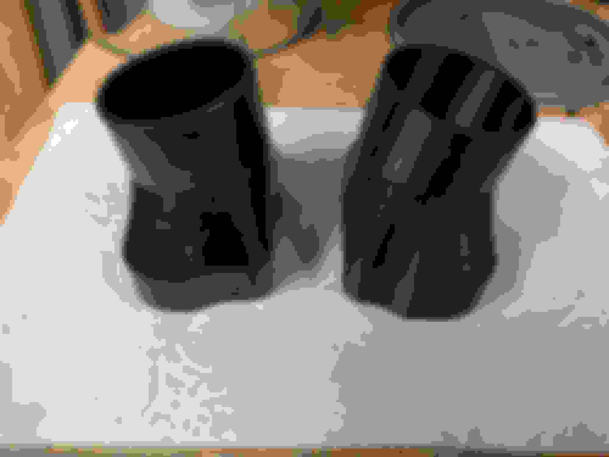
Hey guys, thanks for the interest. Travel, the holidays, more travel, work, and some extreme weather have limited my time on this, but I always knew it was going to move slowly. Anyway, I got the right side designed following the same process, and then after several iterations figured out the optimum settings for the printer and have prototypes of both the adapters done. The right side is pretty much a mirror image of the left, but the geometry of the little bump at the bottom is different. Here they are printed in black ABS.
Once I got the printer settings right to get good adhesion between the layers, they come out very strong. There won't be much load on them but vibration is potentially an issue. It is easy to tweak the design and print a new set if necessary.
For the outlet at the rotor, I was thinking about the Sneed kit, but my current plan is to do something like this guy did for his S2000: https://robrobinette.com/S2000BrakeDucts.htm
For the outlet at the rotor, maybe I am overthinking this but I want to get the air to the center of the rotor. I have done a conceptual design, inspired by similar stuff that others have done for S2000s, 911s, etc.
This would replace the "Rotor Protection Plate" Mini part #34116858073/4 and direct the air into the center of the rotor so it will exhaust through the middle, thereby cooling both sides equally. I am guessing at the dimensions and geometry up to this point, I hope to get some quality time in the garage this weekend to pull off the plate and get some measurements and see what happens when idea meets reality. Obviously a 3D printed piece isn't going to stand up to the heat generated but it will serve to prove the design and fit, then it can be committed to carbon fiber or aluminum.
I would love to work with one of our vendors at NAM to make this available to all, I'm doing the design for the fun of it so if anyone wants to take this to production in carbon fiber all I ask is set #1 of the production run. PM me if interested.
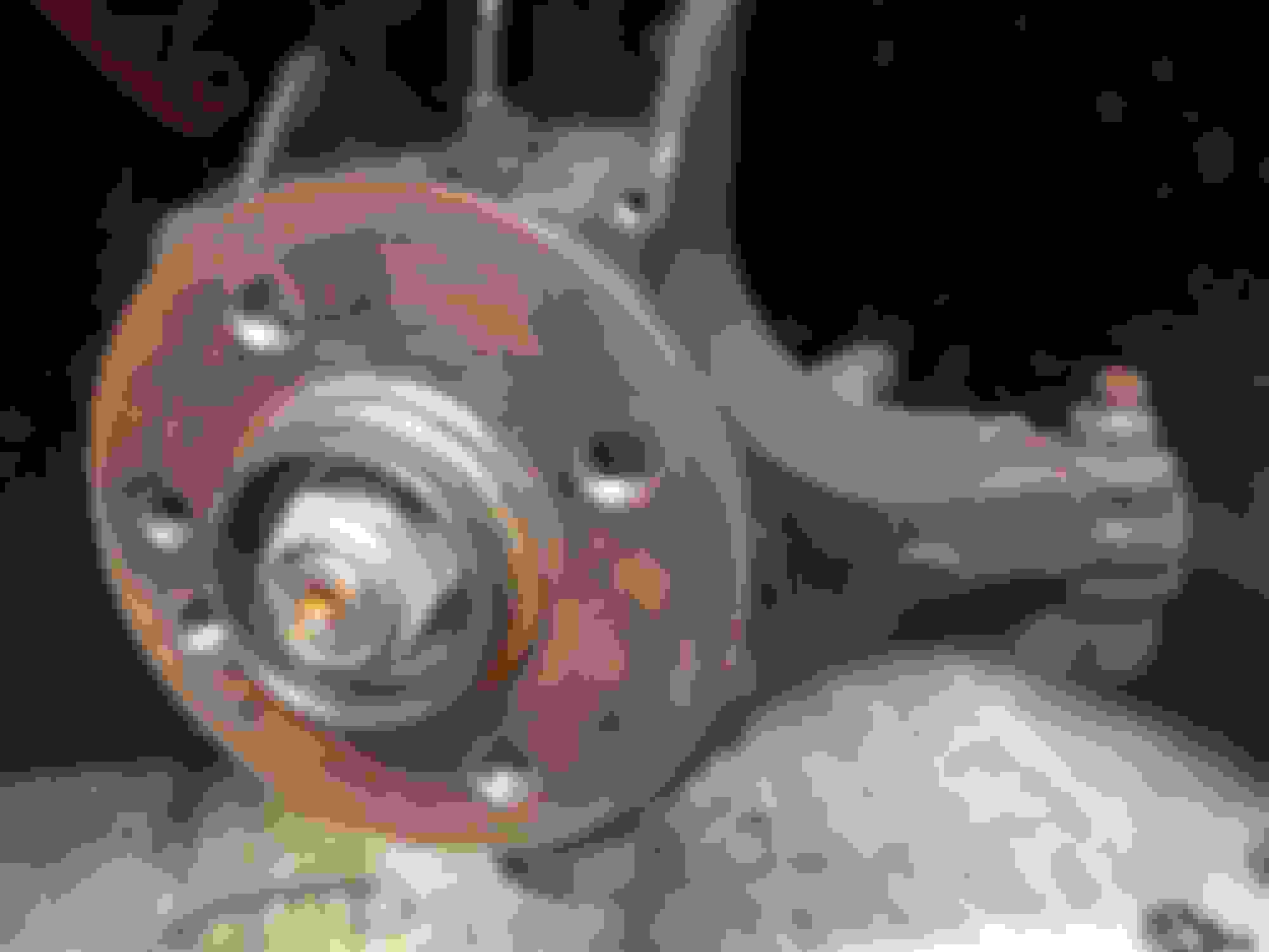
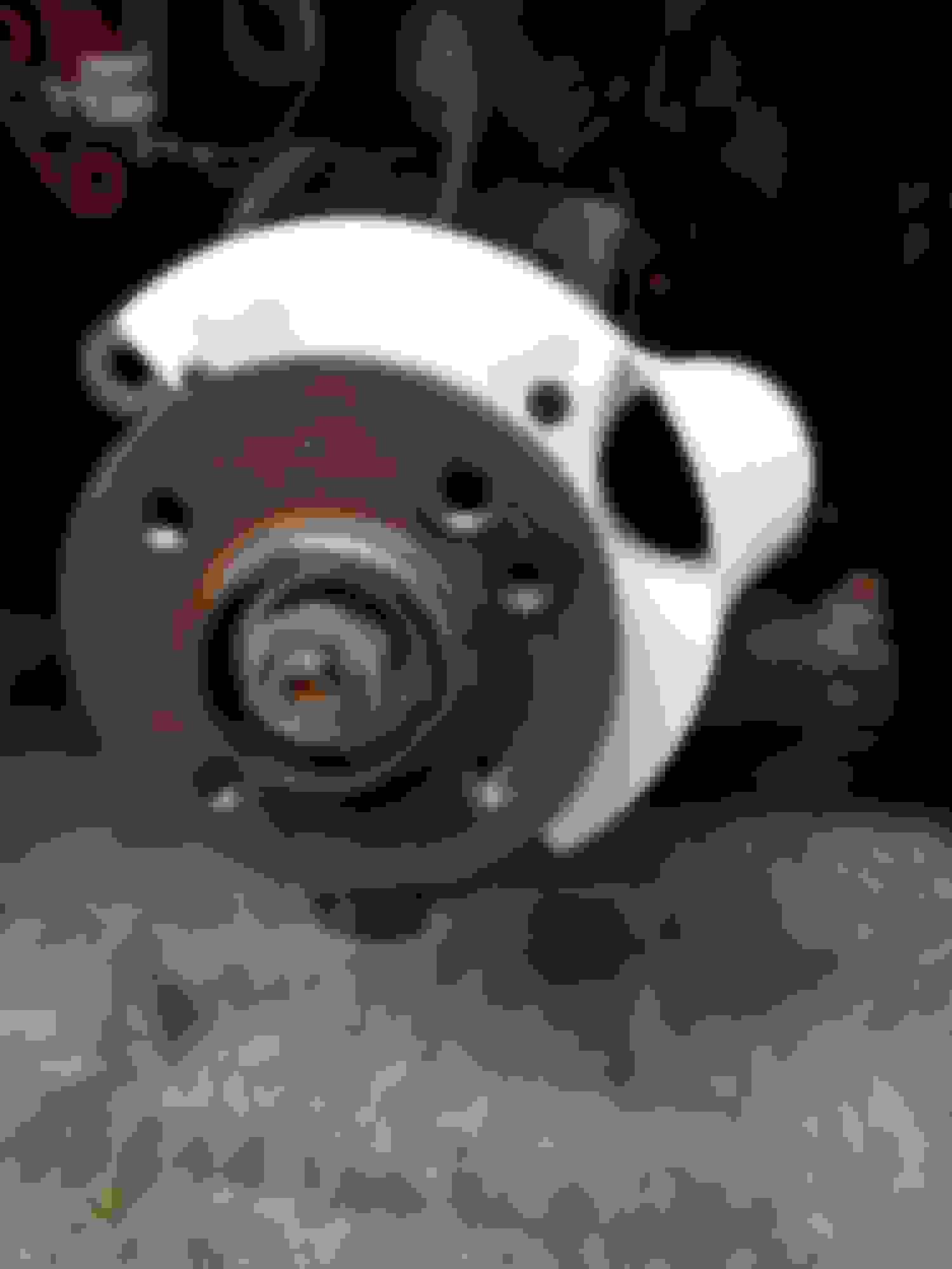
I did manage to get some quality time in the garage last weekend so I pulled off the left wheel, caliper, rotor, and protection plate. There's a nice spot at the back of the wheel carrier for the duct to come in to the rotor.
The protection plate is far from flat, so I decided my original idea of just fixing a duct outlet to the protection plate wasn't going to work very well.
I marked up the protection plate on the back side to get an idea of where the curve in the wheel carrier is, and also traced the outline of the protection plate and hole locations to make a cardboard template so I could get all the geometry into the CAD program. Here's the back side of the protection plate with the curve of the wheel carrier and an approximate circle of a duct outlet marked in silver.
While I had the rotor off I measured the inside diameter (200mm). Also looks like it will be time for new pads and rotors soon.
I got busy with FreeCAD and got all the dimensions from the template entered to update the conceptual design I showed above. After looking at what's available for a lot of other cars, I was surprised at how much is out there for S2000s, BRZs, etc. I was also envious at first, but since there are so few options for the MINI it just gives me an excuse to design my own. I got some good ideas, mainly I decided that I didn't need to hit all four mounting points, just enough to make it stable and contain the air for part of the wheel rotation. I updated the design, then just because I could, I ray traced it and applied a carbon fiber texture map.
Sunday I was walking the dog and thinking about how to actually build this. Fresh air and exercise was a great mental stimulus, because I had a great idea. I was thinking that I could 3D print it, then wrap it in carbon fiber, but how to get rid of the plastic part once the resin had cured? Then I remembered that one of the filament types available is PVA - which is water soluble. Bingo! I'll do a full size print to check the fit, then shrink it by a few mm so I can overlay the carbon fiber cloth. Then toss it in the sink once the resin is cured. From messing about with boats I'm well acquainted with fiberglass fabrication so this should be pretty easy.
I'm sure reality will collide with expectations more than once before I'm done, and I have a lot of busy weekends coming up so this will take a while.
After making some adjustments to the design I did a full size print in ABS and tried the fit. Wheel side:
And from the back with the rotor in place:
The template really worked well as the fit is nearly perfect. I used the shop vac to blow air through the duct, it does a great job of directing air into the center of the rotor so it comes out through the center vents. I need to shift the position of the round connector for the flexible duct a little bit as there's no clearance on the bottom, once I get that change made the next step is to order some PVA filament, carbon cloth and high temperature resin.
Looks really good. Are you concerned about running the duct behind the axle, or is there plenty of room for that?
I'm worried about the radiant heat coming off onto the part when parked, do others make these out of carbon? I really like what you have done, I wonder if you could have modified the steel dust shield by welding a tube on it?
You have me really interested, I'll have to look at doing something similar when I put on my Wilwood BBK this spring (I'm not dedicated enough to do stuff in a 30 degree garage).
I think there's plenty of room to get the duct from the inside of the wheel well out to the rotor. The tight spot will be getting it past the transmission on the inside of the wheel well liner.
I share your concern about the radiant heat from the rotor. I was inspired by lots of similar things that I saw for 911s, S2000s, etc. so that gives me some confidence. Also I found an epoxy that is good up to about 600F that I plan to use. Besides, this should keep the rotor a lot cooler to start with.
I thought about welding a tube into the shield, other people have done that. I don't have a welder, nor the metalworking skills to use it, and it would be really difficult (for me anyway) to make the transition down to the shape to direct air into the rotor center. The nice thing about fiberglass or carbon fiber is it is really easy to create arbitrary shapes that would be very difficult in metal. The only tools you need are scissors, a plastic cup to mix the resin in, and a disposable paintbrush. I started with fiberglass when I was 10, fixing the dings in my surfboard so I'm going with what I know.
CAD plus the 3D printer makes it really easy to design and build test pieces to optimize the design, I am surprised at how quickly this is going.
I have been corresponding with someone who has fitted cooling ducts on an R56, he advised me that 2" ducting is required to get it past the transmission so I need to update the design. OK, that's easily done.
Today I was replacing the alternator/AC drive belt, while I had the wheel well liner out I test fitted the adapter to the duct from the bumper. This is the original version for 2.5" duct. In the picture it looks like there is a lot of clearance, it is actually a bit tighter than it looks.
Since I have to print a new set anyway for 2" duct, I'm going to angle the round part away from the AC compressor pulley for a bit more clearance.
I finally got some PVA filament for the 3D printer so next week I'm going to try to print the form for the ducts at the rotor to lay carbon onto.
I have been trying to get a successful PVA print, so far I can't get it to stick to the print bed. I have a few more ideas to try with the 3D printer, need to get back to it after travelling for 3 weeks.
I'll put up a dropbox folder with the design files, let me know if you have CAD software and what formats you can handle, I'll try to export.
I finally figured out how to print with PVA. PVA is generally used as a "support" filament in printers that have two extrusion heads to enable printing shapes with overhangs that wouldn't otherwise be possible. It really isn't intended to make larger shapes like I'm trying to do so it took a bit of experimenting to figure out right settings.
I got the form printed printed in PVA and since I had some scraps of fiberglass cloth and some polyester resin in the garage I did a proof of concept layup. I only had enough to do 3 layers of cloth so it is pretty thin. After the resin cured I dropped it in the sink and was able to dissolve out the PVA. Then I cleaned it up with the dremel. Overall it worked as I had hoped, and I learned a few things to apply to the next iteration - mainly to make the flat plate a lot thicker to make the layup easier.
I ordered the carbon fiber cloth and high temp resin and did some first experiments with how to layup the cloth. Handling the cloth is really difficult as it tends to just come apart in your hands. The tricky part is the tube, there is braided carbon fiber tubing available that can expand or contract around a shape so I'm thinking of using a combination of that and flat cloth. I also need to print a new set of forms.
mbwicz PM'd me and offered to send me some carbon cloth he had left over. Of course I said "sure" and a few days later a package showed up with a few yards of heavy carbon twill. Thanks man!
Conveniently, my wife was out of town this weekend so I brought the 3D printer home from work and printed out forms for the rotor plates in PVA. Using the cloth from mbwicz and the high temp epoxy that I had ordered (here: https://store.acpsales.com/products/...re-epoxy-resin) I laid up the left side rotor plate. I used about 8 layers of carbon, once the epoxy had set I trimmed and sanded with the dremel and then put it in the sink to dissolve out the form. It worked great, though it took some sanding to get the final bits out since the epoxy had soaked into the form in places. Here is the left side in carbon next to the PVA form for the right side. The plate is amazingly stiff and weighs only 2.4oz. If I had a vacuum bag system to squeeze out the excess resin it would be even less, but at 2.4oz it doesn't really matter. Not sure if I will give it a gloss coat or not, it is going to live a dusty life hidden behind the brake rotor so aesthetics don't really matter. I plan to add a bead around the round hose inlet to make sure the hose and clamp don't slip off.
I also printed up a set of the revised adapters for the bumper side ducts, these are for 2 inch hose and have a small angle towards either side.
Just have to do the right side rotor plate in carbon then it's time to order the hose and put it on the car.
Have you found a way to route the brake duct hose around the suspension and to the rear of the rotor the way you have it planned (Pictures?)? That is where I am stuck. So I am going to route to an area radially inward from the caliper on the front side of the rotor. I have ordered hose and going to see if I can make it fit before I do anything major.
the Sneed guys say you have to use 2" duct to get past the transmission on the left side. I am putting together an order for new rotors and pads, I plan to get the ducting and install everything at the same time. I'll post pics when I do.
Learned a new trick for 3D printing with ABS, Acetone Vapor Polishing. Google it for details. Really simple, here's a before and after. The acetone vapor slightly melts the outer layer of the ABS so the ridges between the printed layers dissolve into each other and the surface really smooths out. This will make the layers adhere better and reduce stress concentration so over all it will be stronger.
I use Sneed bracket at the rotor, I did not like the design so I fslipped them and bent thrm around so the air is all going into the center of the rotor instead of the face of the rotor, saw a nice temp drop
I just got a section of 2" hose and 2-1/2" hose and will be looking at which I can route the best. I have given thought to using a bit of both.
OK, I see how to get by the tranny. But what I haven't figured out is how to get by the strut tower on the inside of the engine bay or out and over/around the suspension in the wheel well to get to the rearward end of the rotor. Any ideas?
 12-01-2016, 11:16 PM