When you click on links to various merchants on this site and make a purchase, this can result in this site earning a commission. Affiliate programs and affiliations include, but are not limited to, the eBay Partner Network.
Brought the car home on Saturday March 4th. Sadly, the issue remains. I get a CEL immediately upon the re-start of the car after having driven any distances. More on that another time...
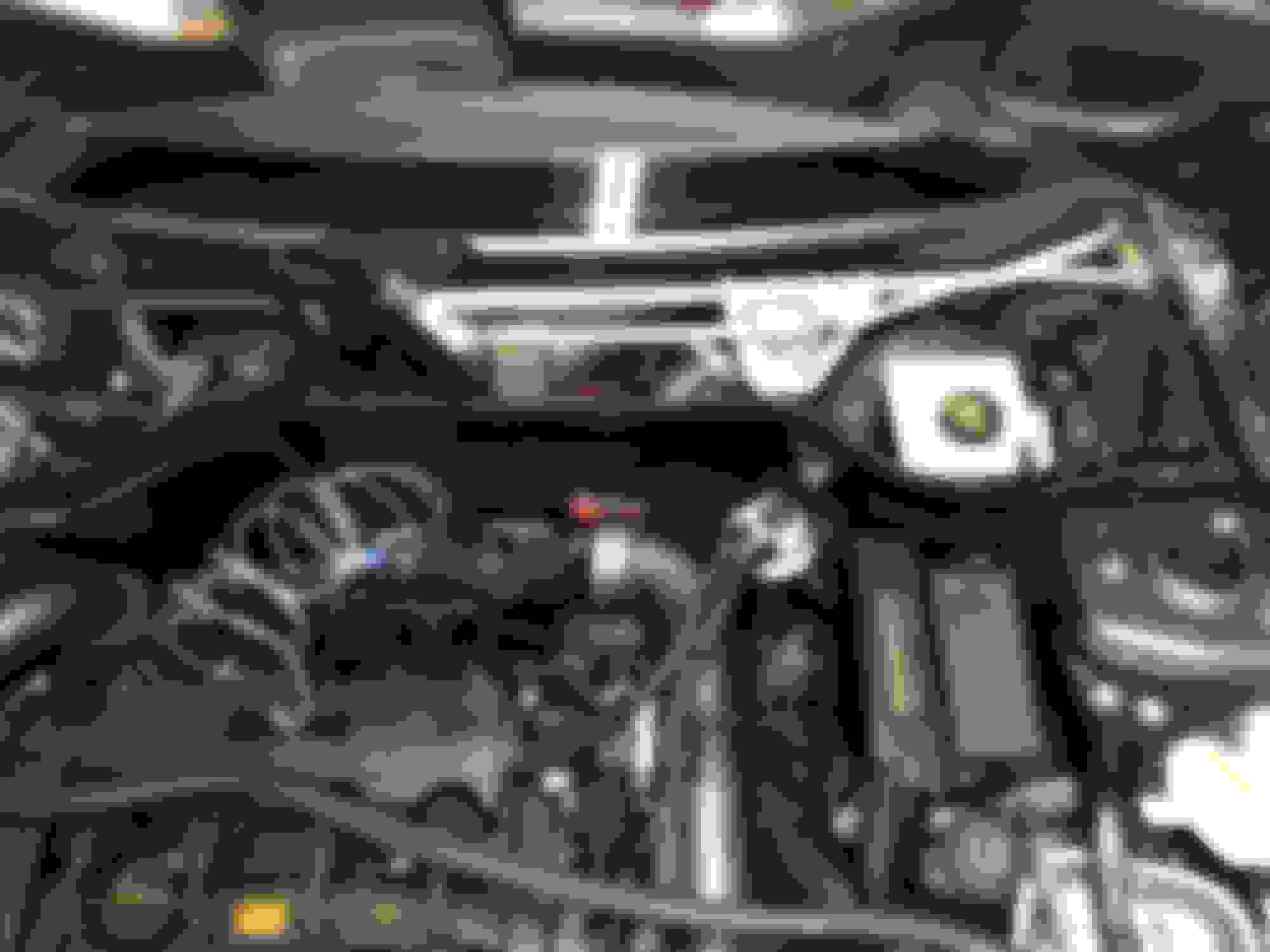
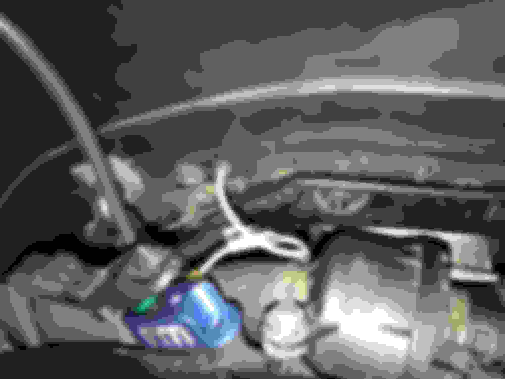
So after a busy week at work I was able to set aside a day to tinker. Initially, I had planned on installing the exhaust, but got drawn into installing the boost/vacuum and H2O temp gauges. Getting anything thru the firewall in this car, without drilling holes (not a good idea) requires the removal of the windshield wipers and cowling. Here are a few pictures.
Cowling removed for accessing the wiring harness port (cover removed) in the upper right.
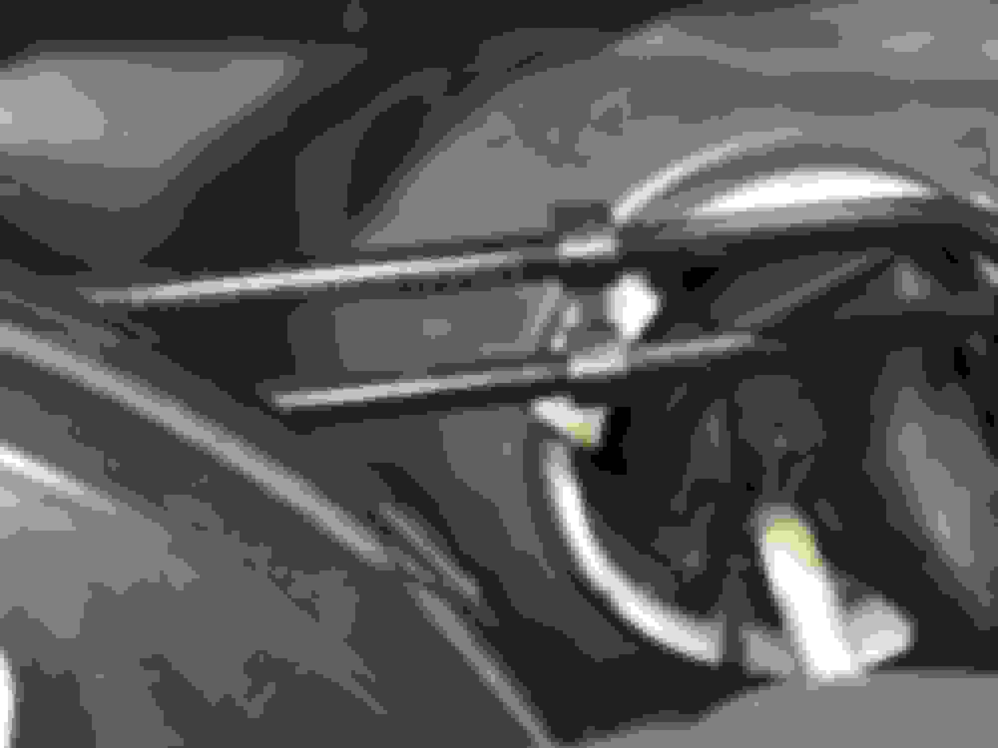
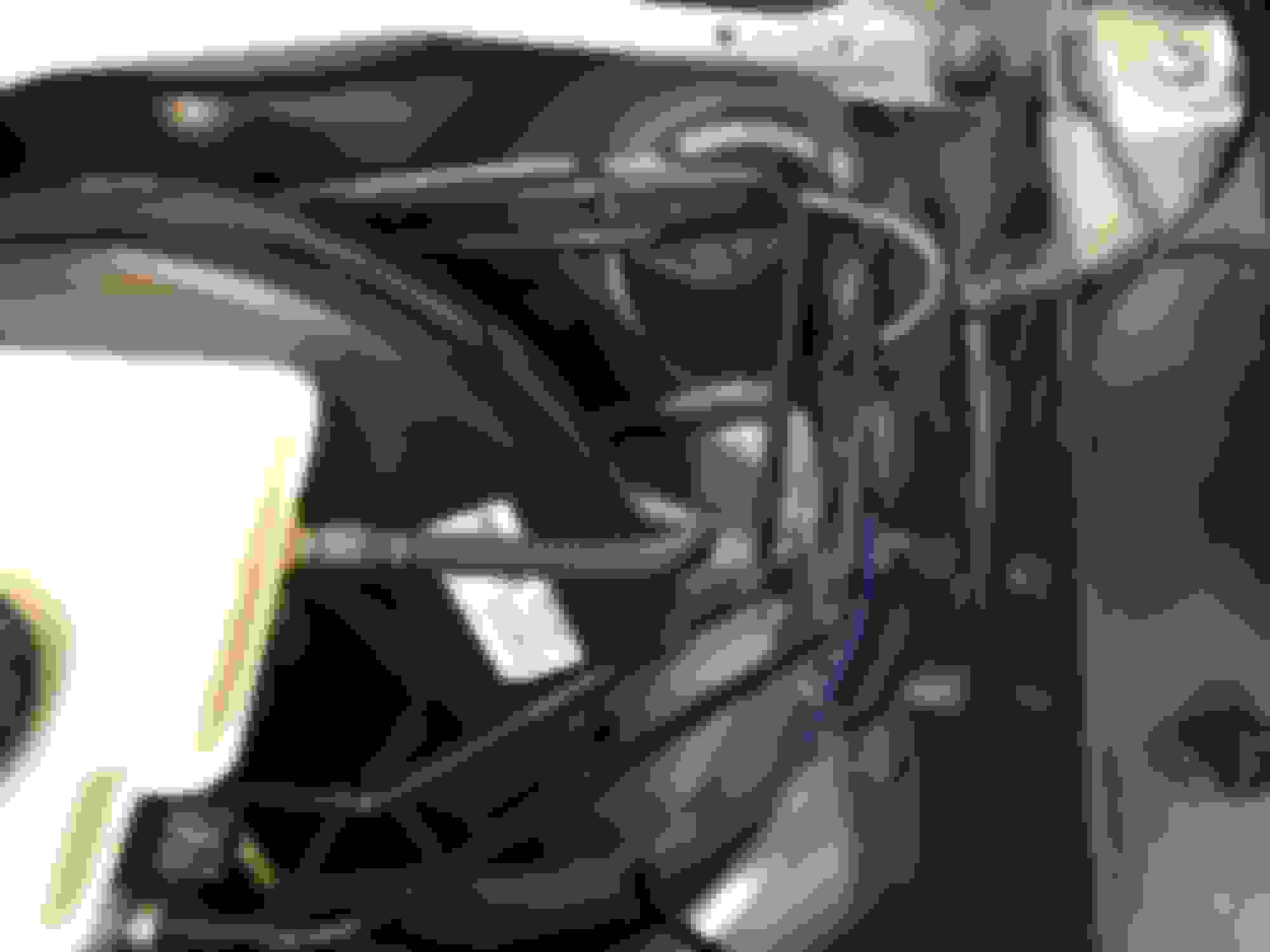
This is where I routed the wire and boost/vacuum tube.
Soft bends to keep the tube from kinking and carefully placed zip ties to minimize movement and chafing.
Zip ties to keep things in place
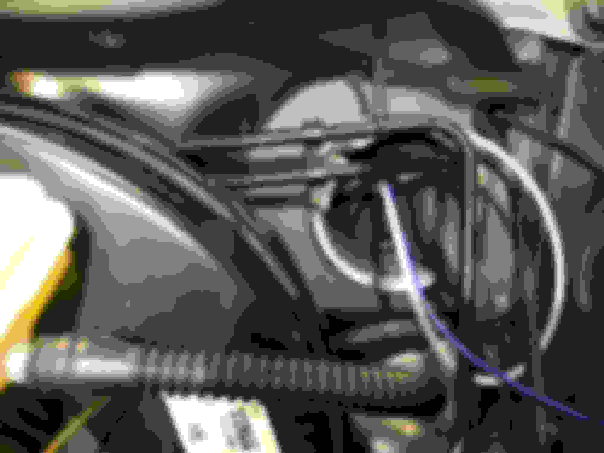
Soft bend to keep from kinking, plus the excess line will move with the engine under hard acceleration. Rubber grommet in the plastic liner to reduce the likelihood of wear on the semi-rigid tubing.
Tube and temp sender wiring.
Cover installed, wiring routed with existing wires and zip tied into place. Ideally I would have used wire loom to protect the wire but with no moving parts and a secure mount this should be fine. The portion in the engine bay will have split loom.
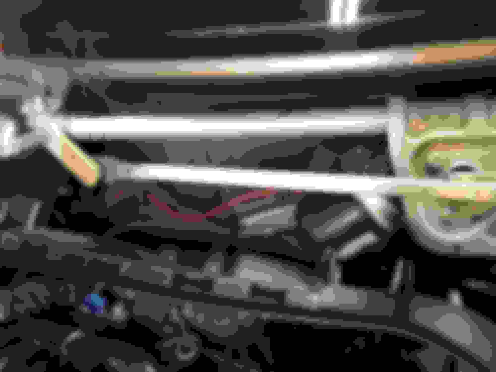
The boost tube mounted under the AEM air-box.
Vacuum / Boost line
up-close of a similar view at the airbox
Routing away from heat and desbris.
The mounting plate needed some modifications and a little form shaping but turned out really well. By the way... the mounting holes on the back of your tachometer/info center are 9.5cm on center in width. Just in case you were wondering.
Finished product...
I also routed my audio and power cables discreetly in through the dash.
Seahawks!!! And an up close look at the carbon fibre wrap material.
The wires now come out from behind the dash for a much cleaner look. Should have replaced that white 1/8" audio cord with a black one. Hmmm... maybe I still will.
Looks tidy
Another view of the audio and power wire routing through the dash
I first installed white LED's but the light wasnt balanced side to side and the color was wrong so I switched to Amber colored LED lights to better match the factory lighting.
I swapped out the white for Amber colored LED bulbs
Aaahhhh... that's much better.
Last edited by Absolutjh22; 03-26-2017 at 01:02 AM.
Last weekend my daughter (10 years old) and I got the exhaust installed. Overall, a pretty simple process to remove the factory exhaust. The factory exhaust has got one bolt at the catalytic converter, and 4 rubber hangers that need to be slipped off. I used a panel removal tool to expand the clamp at the catalytic converter, and to aid in sliding the hanger mounts over the nub on the factory exhaust (the Milltek unit does not have the same nubs on the hangers).
The Milltek exhaust ships in 7 pieces (front section, mid-pipe with resonator, y-pipe, 2 mufflers, and 2 tailpipes, plus 4 smaller exhaust pipe clamps and 2 larger exhaust pipe clamps) that need to be loosely assembled and then adjusted to the ideal fit. I found that once I got each of the sections set roughly where they needed to be I could use a floor jack at the y-pipe to lift the whole exhaust up into the channels where they will ultimately live, leaving enough space for the whole unit to move under load. From there I adjusted the mufflers so that the tailpipes fit nicely into the bumper cutouts. Once all the pieces were aligned where I wanted them, I tightened the pipe clamps down to hold the whole thing together in place (about 40 lb ft each). I let the floor jack down and the whole thing stayed right where I wanted it.
Catalyst back
Catalyst to mid-section
Front section at hangars
Resonator in the mid-section
Mid-section to Y-pipe
Y-Pipe after the midsection which has the resonator (not pictured).
Left Muffler w/o tip
Left muffler w/ tip
Right muffler w/ tip at Y-pipe (loose fitment)
Everything tightened up and set in place.
Underside view
Final fitment, rear-view.
Rear view
Left polished tip. I have it sticking out a bit; cause I can.
Right polished tip
Great build quality (time will truly tell though)
Me and my daughter's reflection. SO shiny...
Megaphone. Girls just want to have fun
Last edited by Absolutjh22; 03-26-2017 at 01:20 AM.
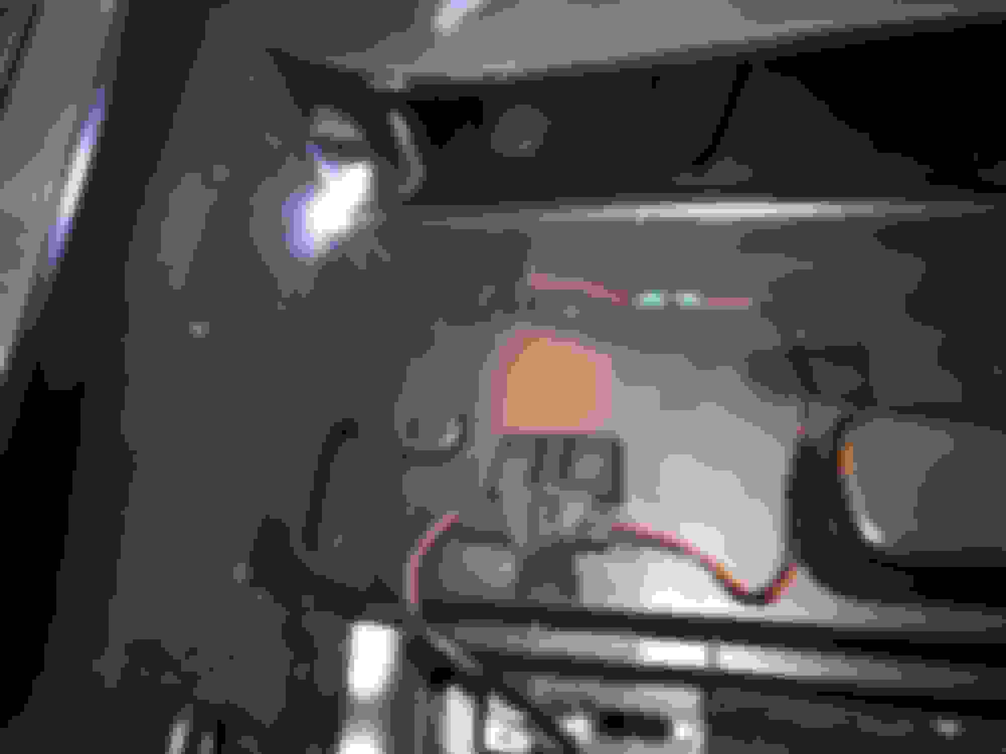
Add-a-Fuse are a great way to supply 12v power to an accessory. In this case it's Fuse 42 (Charger sockets front and rear) which happens to be switched power.
I was able to get the temp and boost gauges wired up over the last week, as well. I have added gauges to several vehicles and this vehicle was, by far, the most difficult to work on for routing the various wiring, and boost/vacuum line. Adding the water temp tap was fairly simple, but required a little finesse and adjustments. The inline sensor port ends up directly under the factory fresh-air intake. I needed to remove the radiator coolant tank, and fresh air-intake inlet tube. From there, I removed the factory plastic coolant hose connector and replaced it with an M7 style coolant hose connector with an 1/8" NPT threaded tap. The sender has to mounted at 90 degrees so that it doesn't hit the air-inlet tube.
Add to that the complexity of locating the appropriate wire to tap into for the lighting, and a switched ignition source and it was almost enough to make me go crazy. Though, admittedly, I have a need for "perfection" which takes even more time. None-the-less, I am very pleased with the finished results.
By the way, it's the Blue 16 gauge wire located in the lower wiring harness at the "foot well module".
This is the wire you want to tap (parking lights). Ideally I would have been able to tap into the dash lights and be able to dim the gauges, but no such luck (patience) locating that particular wire.
I ended up using an "add-a-fuse", coming off of the 12v charging port (Fuse #42, I think), as it is switched power, and ran the wiring up behind the glove-box and through the center stack and then over to the "ignition" lead on the gauges so that they only get power when the ignition is "on".
Last edited by Absolutjh22; 03-24-2017 at 08:40 PM.
One of the things that has been a bit annoying is the lack of light in the cargo area. I upgraded to an LED bulb in the original light, but that wasn't quite enough. So... I got creative.
I bought a roll of (adhesive backed) LED strip lighting, and water-tight wiring connectors, on Amazon and soldered the connections to the factory cargo-light wiring; this is activated by the door switch. The wiring connector allows me to remove and replace the light if it gets broken, etc.
The light output is very bright so I placed a 3/16" red translucent strip at the top edge of the strip light so I don't go blind each time I open the doors. I also removed the entire panel and wrapped it in a clear floor laminate so that the light strip would not get easily ripped off.
Overall, I am pleased with the end results.
Let there be light...
water tight connector to make it possible to disconnect, and/or replace the light strip. I used Gorilla tape to secure and protect the lead wire.
up-close of the light strip (prior to adding the 3/16" red translucent vinyl to the top leading edge)
Last edited by Absolutjh22; 03-26-2017 at 01:31 AM.
A lot of really good work done here for sure, and definitely worth it on your way cool Clubman. A lot of detailed work, too. Now I've gotta go take a rest after all this! Whew.
And that Milltek exhaust is awesome on there. Kudo's to you and your daughter!
 03-13-2017, 11:29 PM