R50/R53 :: Hatch Talk (2002-2006) Cooper (R50) and Cooper S (R53) hatchback discussion.

R50/53 R53 indicator stalk wiring

Thread Tools
 
Search this Thread
 
  #1  
Old 07-22-2017, 12:46 PM
Nate78's Avatar
Nate78
Nate78 is offline
1st Gear
Thread Starter
Join Date: Jul 2017
Posts: 17
Likes: 0
Received 0 Likes on 0 Posts
R53 indicator stalk wiring

Hi all,

I'm currently trying to figure out the indicator stalk wiring, there are 8 wires, they are
Brown
Yellow/red
Black
Grey/black
Purple
Yellow/white
Blue
White

Can anyone help me label what each cable controls?

Thank you in advance for any help given
 
  #2  
Old 07-22-2017, 01:11 PM
Whine not Walnuts's Avatar
Whine not Walnuts
Whine not Walnuts is offline
OVERDRIVE
Join Date: Mar 2013
Location: Fuquay Varina, NC
Posts: 5,490
Received 625 Likes on 554 Posts
Pretty sure the Bentley Manuals have wiring diagrams in the back. Hopefully somebody will see your post and advise.

Try some google searches that will most likely bring you back here.
 
  #3  
Old 07-22-2017, 01:14 PM
Nate78's Avatar
Nate78
Nate78 is offline
1st Gear
Thread Starter
Join Date: Jul 2017
Posts: 17
Likes: 0
Received 0 Likes on 0 Posts
Hi, thanks, yeah that's how I found this site, I have the Haynes manual but that doesn't show anything, someone must know something! Haha
 
  #4  
Old 07-22-2017, 02:12 PM
rkw's Avatar
rkw
rkw is offline
OVERDRIVE
Join Date: May 2005
Location: San Francisco
Posts: 8,233
Received 120 Likes on 105 Posts
https://www.newtis.info/tisv2/a/en/r...switch/io3VSCB

The Bentley Manual wiring diagrams are really awful to use. They are basically printouts/screenshots from the original interactive wiring diagrams.
 

Last edited by rkw; 07-22-2017 at 02:17 PM.
  #5  
Old 07-22-2017, 02:25 PM
Nate78's Avatar
Nate78
Nate78 is offline
1st Gear
Thread Starter
Join Date: Jul 2017
Posts: 17
Likes: 0
Received 0 Likes on 0 Posts
Thanks, looking at that it looks like the left and right indicators share the same wire,
Is that correct?
 
  #6  
Old 07-22-2017, 02:41 PM
Nate78's Avatar
Nate78
Nate78 is offline
1st Gear
Thread Starter
Join Date: Jul 2017
Posts: 17
Likes: 0
Received 0 Likes on 0 Posts
I've swapped my way for an omex 600 and gone for a dash2, so the old ecu, bm1 and all wiring has been removed to make way for a more tidy custom loom, if the left and right indicators share the same wire ( I'm guessing different values are sent for left and right and the way or bm1 decodes) is it possible to use adopt that on a simple loom?
 
  #7  
Old 07-22-2017, 03:18 PM
rkw's Avatar
rkw
rkw is offline
OVERDRIVE
Join Date: May 2005
Location: San Francisco
Posts: 8,233
Received 120 Likes on 105 Posts
Originally Posted by Nate78
Thanks, looking at that it looks like the left and right indicators share the same wire,
Is that correct?
Yes, looks that way.
https://www.newtis.info/tisv2/a/en/r...switch/Z5bfDKS
 
  #8  
Old 07-22-2017, 03:28 PM
Nate78's Avatar
Nate78
Nate78 is offline
1st Gear
Thread Starter
Join Date: Jul 2017
Posts: 17
Likes: 0
Received 0 Likes on 0 Posts
That's what I thought, I hoping it's possible to modify the pcb so that the left and right indicators use different pathways
 
  #9  
Old 07-22-2017, 03:55 PM
Nate78's Avatar
Nate78
Nate78 is offline
1st Gear
Thread Starter
Join Date: Jul 2017
Posts: 17
Likes: 0
Received 0 Likes on 0 Posts

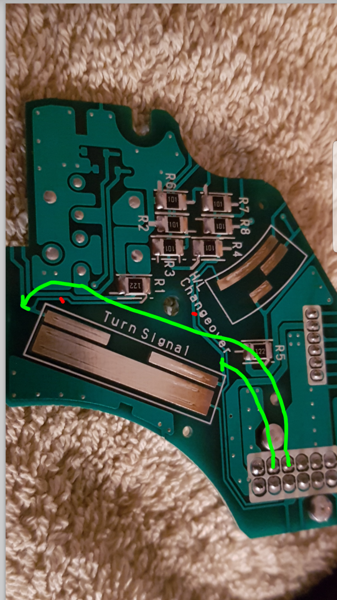
Red - cuts in old circuit
Green - new wires to unused pin
I've seen this done on other pcb,
But I may be over simplifying things and totally wrong
 
  #10  
Old 07-22-2017, 04:14 PM
rkw's Avatar
rkw
rkw is offline
OVERDRIVE
Join Date: May 2005
Location: San Francisco
Posts: 8,233
Received 120 Likes on 105 Posts
You need to probe the signal and see how the BCM distinguishes between left and right. Since they share the same wire, there must be something different in the signal that is sent.
 

Last edited by rkw; 07-22-2017 at 04:20 PM.
  #11  
Old 07-22-2017, 04:28 PM
Nate78's Avatar
Nate78
Nate78 is offline
1st Gear
Thread Starter
Join Date: Jul 2017
Posts: 17
Likes: 0
Received 0 Likes on 0 Posts
I done a continuity test and the left indicator gave a reading of 300 and the right gave a reading of 1200 (might of been the other way round)
This is all guess work
But if I cut out the resisters? (The small square bits) And make the returns clean, will that not make it into a simple on/off?
I think you are right in that it does at the moment send a signal that gets decoded into whether it's a left it right signal,
Obviously I'm no electrian and all this is me grasping at straws
The 12 pin I'm guessing is the power in as it is the only fused wire. I think it is certainly worth a try as a replacement is only £9 on eBay
 
  #12  
Old 07-22-2017, 04:35 PM
rkw's Avatar
rkw
rkw is offline
OVERDRIVE
Join Date: May 2005
Location: San Francisco
Posts: 8,233
Received 120 Likes on 105 Posts
Originally Posted by Nate78
if I cut out the resisters? (The small square bits) And make the returns clean, will that not make it into a simple on/off?
...
Obviously I'm no electrian and all this is me grasping at straws
Me too! Seems like the right direction, but I think both of us know just enough to be dangerous!
 
  #13  
Old 07-22-2017, 04:39 PM
Nate78's Avatar
Nate78
Nate78 is offline
1st Gear
Thread Starter
Join Date: Jul 2017
Posts: 17
Likes: 0
Received 0 Likes on 0 Posts
You could be right, I will be consulting an auto electrician, I couldn't do the mod anyway, what's the draw on a indicator relay? It can't be much?
 
  #14  
Old 07-22-2017, 04:43 PM
Nate78's Avatar
Nate78
Nate78 is offline
1st Gear
Thread Starter
Join Date: Jul 2017
Posts: 17
Likes: 0
Received 0 Likes on 0 Posts
I'm thinking about connecting the live and ground to a battery and seeing what is sent down each wire as I indicate left/right use side lights/ main beam and high
 
  #15  
Old 07-22-2017, 05:18 PM
rkw's Avatar
rkw
rkw is offline
OVERDRIVE
Join Date: May 2005
Location: San Francisco
Posts: 8,233
Received 120 Likes on 105 Posts
Originally Posted by Nate78
what's the draw on a indicator relay? It can't be much?
There are no indicator relays. The indicator bulbs are connected directly to the computer, which blinks them under software control. The turn signal clicking is not a relay, but emitted from a speaker in back of the speedometer.
 
  #16  
Old 07-23-2017, 12:37 AM
Nate78's Avatar
Nate78
Nate78 is offline
1st Gear
Thread Starter
Join Date: Jul 2017
Posts: 17
Likes: 0
Received 0 Likes on 0 Posts
It's all very complicated then !
 
  #17  
Old 07-23-2017, 04:45 AM
Nate78's Avatar
Nate78
Nate78 is offline
1st Gear
Thread Starter
Join Date: Jul 2017
Posts: 17
Likes: 0
Received 0 Likes on 0 Posts
I've taken the stalk apart and it looks like I will be able to wire it up so it will control a few relays with a negative switch
 
  #18  
Old 07-23-2017, 08:39 AM
1qwkmini's Avatar
1qwkmini
1qwkmini is offline
3rd Gear
Join Date: Mar 2013
Location: Bayfield, Ontario
Posts: 296
Received 36 Likes on 31 Posts
Post your wiring when done!!
I'll share what I did for turn signals, but I didn't use the signal stock, just used a simple 2 pole switch on the dash..center off/left/right

You can wire in a simple flasher relay to the power side (centre of the switch) and then locate the turn signal wires near the BCM (one wire controls front and rear). Wire them to either side of the switch and you have signals.
I'd like to return to using the turn signal stalk (more convenient) so let me know if you find a working solution.

BTW you can use the same flasher and turn signal wires to power the 4 way flashers...just need a double pole switch...common feed the power supply from the flasher and keep the outgoing signal separate to the turn signals.

On your own for headlights...mine are removed.
 
  #19  
Old 07-23-2017, 08:58 AM
Nate78's Avatar
Nate78
Nate78 is offline
1st Gear
Thread Starter
Join Date: Jul 2017
Posts: 17
Likes: 0
Received 0 Likes on 0 Posts
I will post pics.( if it's a success) hah

I'm using dominator 2.0 headlights
 
  #20  
Old 07-29-2017, 02:13 PM
Nate78's Avatar
Nate78
Nate78 is offline
1st Gear
Thread Starter
Join Date: Jul 2017
Posts: 17
Likes: 0
Received 0 Likes on 0 Posts


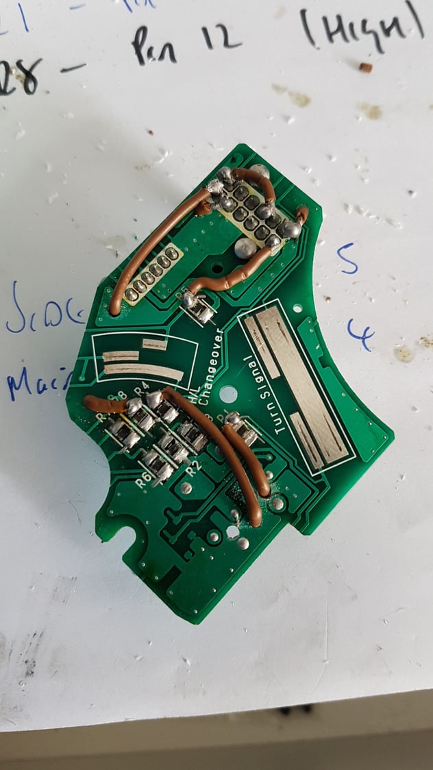
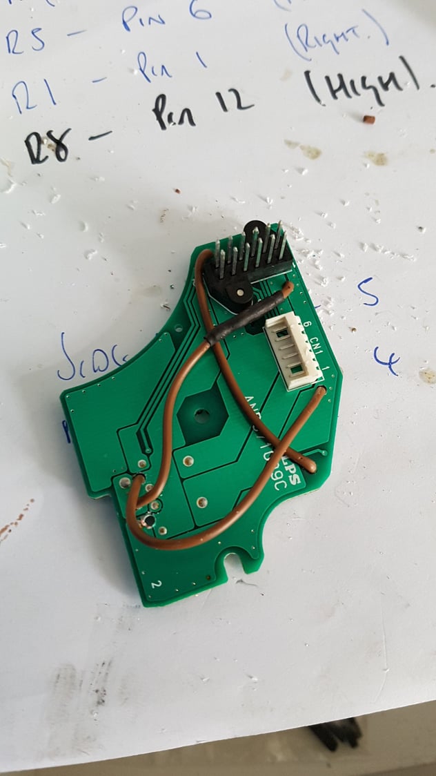
here is the completed wiring, I've tested each operation of the stalk and it looks like it will work,


All times are GMT -7. The time now is 01:46 PM.