When you click on links to various merchants on this site and make a purchase, this can result in this site earning a commission. Affiliate programs and affiliations include, but are not limited to, the eBay Partner Network.
It is a thought. NASCAR uses 2 or 3 centrifugal fans on each side of their cars to cool the brakes and caliper. But, then they have a lot of room for cooling tubes on those cars.
Actually, an in-line centrifugal fan would be better as they tend to be able to develop higher pressure than a muffin fan. The higher pressure would be need to push air through that tube. And they move a lot of air.
Last edited by Eddie07S; 11-25-2018 at 09:19 AM.
Reason: Edit
Meant inline. High heat units are used extensively in the meats fab industry and others. HVAC uses them with thermostats.
I would venture that the rotor cracking is due to the alloy impurities. Older discs could be turned but it appears that today they are a wear item, meant to be replaced rather than serviced. Impurities (crap) in the metal cast causes uneven heat distribution, thus cracking along "fault" lines. I realize that the alloy has to be soft, just wondering if the are better discs out there, perhaps even fabricated (assembled) ones. With brakes used more with auto transmissions, what are F-1 and NASCAR using?
Sorry for thread drift, interesting subject.
I had a random idea to use an inline bilge blower fan, the problem is there's just nowhere to put it. Maybe if this was a dedicated race car I could remove the wheel well liner, washer fluid tank, etc. and make some room but as the pics show, there's no space.
Meant inline. High heat units are used extensively in the meats fab industry and others. HVAC uses them with thermostats.
I would venture that the rotor cracking is due to the alloy impurities. Older discs could be turned but it appears that today they are a wear item, meant to be replaced rather than serviced. Impurities (crap) in the metal cast causes uneven heat distribution, thus cracking along "fault" lines. I realize that the alloy has to be soft, just wondering if the are better discs out there, perhaps even fabricated (assembled) ones. With brakes used more with auto transmissions, what are F-1 and NASCAR using?
Sorry for thread drift, interesting subject.
That is something different from what I was thinking. I was thinking of the fans used in computers when you said muffin fans, and somehow put that in line with the tube. But, I thought one of those wouldn�t develop enough pressure for this application.
Steel and other metals will develop cracks (fatigue cracking) just based on the cycling of a temperature difference between one side and another of a piece, such as the pad surface of a rotor and the vane surface. While imperfections will make a material more susceptible to fatigue cracking, even an ideal, defect free piece will eventually crack with this condition.
Cast rotors, like we use, are actually pretty hard and have a lot of durability. The ones I use are made by the same people who supply rotors for stock car use (they do use cast steel). However, at the temperatures these brakes can get to 1000 to 1600 deg F any steel will loose strength and with that the fatigue strength goes down too. Eventually, with enough heating and cooling cycles, the steel will crack.
Originally Posted by SFMCS
Answered my own question, Brembo makes a carbon ceramic rotor since 2000.
I was once told the carbon rotors for a Porsche were $8000 each.
I had a random idea to use an inline bilge blower fan, the problem is there's just nowhere to put it. Maybe if this was a dedicated race car I could remove the wheel well liner, washer fluid tank, etc. and make some room but as the pics show, there's no space.
Seems like that space issue was the start of this whole adventure. There is just no room under the hood of these cars. I looked at removing things, too, but concluded it wouldn�t help much. Your efforts are greatly appreciated, though.
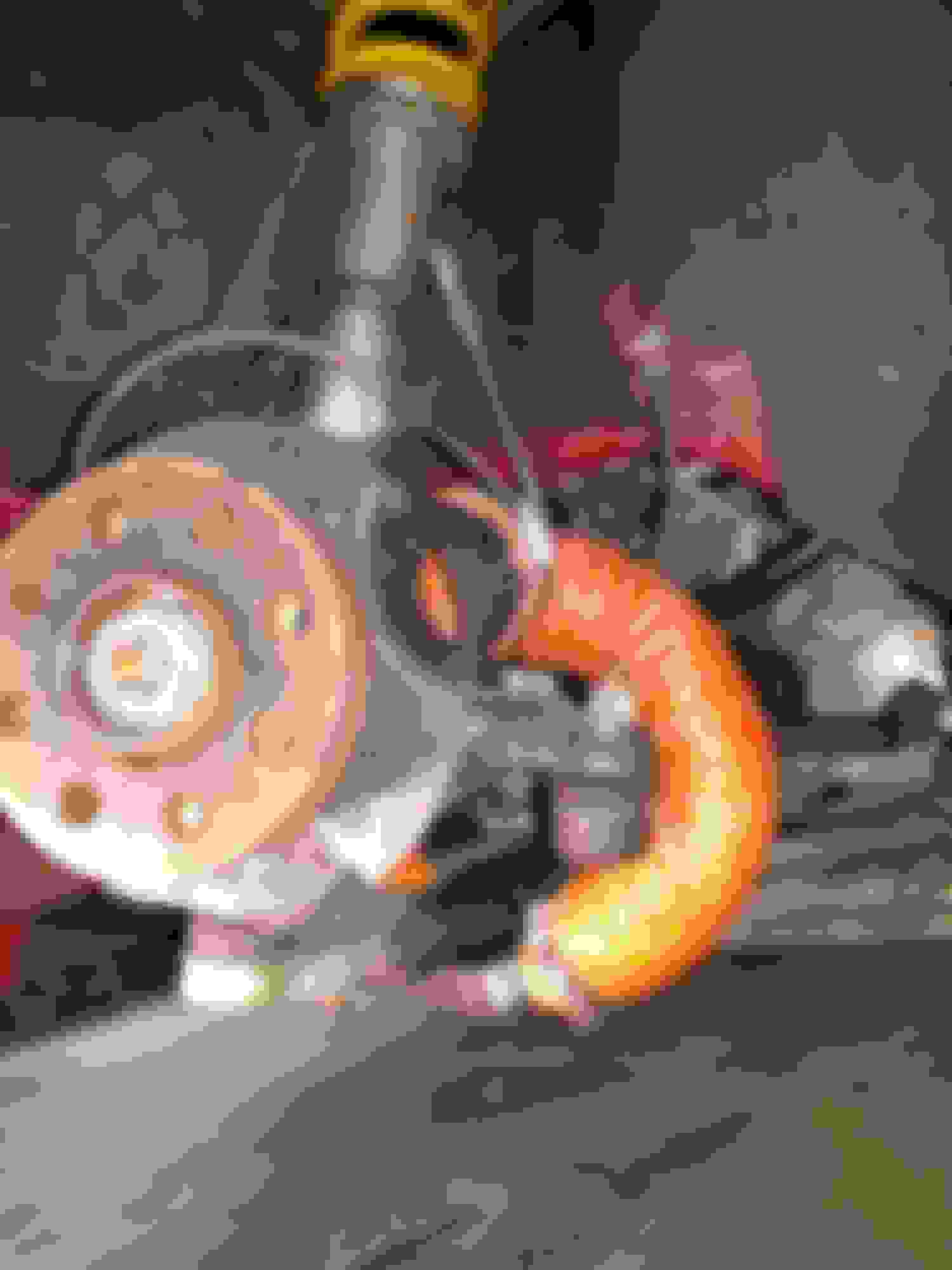
After a few weeks of driving I took the wheel off to see how the system was doing. Now I know why I'm not getting the cooling I was hoping for, after some corners and bumps the swaybar has hit the hose and compressed it to about 1/2 it's diameter. Crap. I was hoping that wouldn't happen. It looks like I could modify the duct that goes between the transmission and the subframe to extend up higher before it bends horizontal, there's another 40mm or so of height if I get the geometry right. A CAD modeling project to save for a rainy day. There's a good picture of the situation in post #53. So 2 years after I started this project, I'm back to stock.
The good news is that all the pieces and parts held up well, except for the hose that got mangled by the swaybar. The carbon plate at the rotor shows no ill effects. And, I have another idea to put a scoop below the lower control arm, and use a short piece of hose to connect it to the plate at the rotor. I think it will fit... not giving up yet!
I wouldnt say it was easy, I had to cut out almost all of the radiator support, and I no longer duct to the back of the axle it's too hard I just point the air at the caliper/axle from the front side. It works so well I have to block it off for tracks like NCCAR (one heavy brake zone)
After a few weeks of driving I took the wheel off to see how the system was doing. Now I know why I'm not getting the cooling I was hoping for, after some corners and bumps the swaybar has hit the hose and compressed it to about 1/2 it's diameter. Crap. I was hoping that wouldn't happen. It looks like I could modify the duct that goes between the transmission and the subframe to extend up higher before it bends horizontal, there's another 40mm or so of height if I get the geometry right. A CAD modeling project to save for a rainy day. There's a good picture of the situation in post #53. So 2 years after I started this project, I'm back to stock.
The good news is that all the pieces and parts held up well, except for the hose that got mangled by the swaybar. The carbon plate at the rotor shows no ill effects. And, I have another idea to put a scoop below the lower control arm, and use a short piece of hose to connect it to the plate at the rotor. I think it will fit... not giving up yet!
I think I saw some place that marketed the scoop under the control arm idea. The idea seem to be good for a dedicated track car, but I doubted that it would stand up to well to our snow around here. Its effectiveness may be dependent upon how low the car is and how much the flow under the car is blocked off with things like splitters. That said, I am very interested in what you come up with, especially if it is easily removable.
I was thinking that an easy test of your ideas would be a leaf blower aimed at the front end scoop and to use a hand held anemometer to measure what is coming out. Like this:
Sorry don't know anything about this one. It is just an example.
It may not be necessary to get absolute values, but values that are consistent and are able to provide a difference comparison between one setup and another.
that's what I did, I got a cheap airflow meter and used my shop vac. I was able to measure the flow drop on my tubing that's when I realized how horrible long tube & bends are for airflow
I think I saw the scoop under the control arm on a Honda or Corvette site. Or maybe Miata. There's lots of different solutions to the problem depending on the car. On 911s there's just a plastic piece that attaches to the control arm to deflect air toward the rotor. Here's a mock-up using one of my duct pieces as the scoop:
That fits inside a 17" wheel, clearance is only tight with the wheel turned all the way out and then there's about 3mm with my wheels. No way this works with a 16" wheel. Yes this would be a track day only thing because of ground clearance. I need to come up with an easy way to attach/detach the scoop, something more elegant that just zip ties.
that's what I did, I got a cheap airflow meter and used my shop vac. I was able to measure the flow drop on my tubing that's when I realized how horrible long tube & bends are for airflow
I just use my shop vac and hold my hand at the end to see if I'm getting good flow. One thing I have considered is making a manometer to use with the shop vac and pulling air through the whole path so I can get a quick relative measure of A vs. B vs. C to see how much flow is lost with bends etc. With a bit of math I could probably convert inches of water to CFM. I probably have most of the bits in the garage already to build it. There's a thread here by a guy who built his own flow bench to port his Porsche 930 heads: https://www.tamparacing.com/forums/g...bench-kit.html
Yes I can crank the wheel all the way both ways, it works out pretty well.
Here's a few pics of my first prototype for the intake scoop. If this looks a lot like one of the earlier parts, yep, that was the starting point. Then I updated the model to change the shape at the end and sweep from one shape to the other. I'm pretty happy with the smooth transition it makes, that should accelerate the flow nicely.
How about a water injection kit to improve efficiency ?
Originally Posted by squawSkiBum
I was gonna reply "???" but then I realized was more appropriate.
You laugh, but I have heard that suggest before. The Gen 2 S with those big scoops up front do pretty well at cooling the brakes in the rain. It is like a fire hose. The worst part about those scoops, though, is that up here in the NE, in the winter, they become salt spray injectors. I wish someone made covers for them, just for that reason.
Seriously, I think it is a pretty good suggestion, but I also think that it comes with some major obstacles. For example, I think the system would have to carefullly control the spray. You don�t want to cool the brakes too much and take the pads out of their �comfort zone�. Also, water is a great absorber of heat. Taking heat out of the rotors suddenly is likely to quickly crack them. I had cracking problems with my rotors just from those scoops blowing air on the inboard side of the rotors when I took the dust shields off and had to put them back on (with my own special modifications...). I think it would take quite a system for a water injection system for the brakes to work effectively. Then there is the question of how much water you would have to carry.
You laugh, but I have heard that suggest before. The Gen 2 S with those big scoops up front do pretty well at cooling the brakes in the rain. It is like a fire hose. The worst part about those scoops, though, is that up here in the NE, in the winter, they become salt spray injectors. I wish someone made covers for them, just for that reason.
Hmm - another design/3D printing project to think about. Or just stuff a tennis ball in the scoops, that was my idea for testing how much of a difference the cooling system makes.
Seriously, I think it is a pretty good suggestion, but I also think that it comes with some major obstacles. For example, I think the system would have to carefullly control the spray. You don�t want to cool the brakes too much and take the pads out of their �comfort zone�. Also, water is a great absorber of heat. Taking heat out of the rotors suddenly is likely to quickly crack them. I had cracking problems with my rotors just from those scoops blowing air on the inboard side of the rotors when I took the dust shields off and had to put them back on (with my own special modifications...). I think it would take quite a system for a water injection system for the brakes to work effectively. Then there is the question of how much water you would have to carry.
Yep, that's all stuff that went through my mind, plus there's the problem that wet brakes won't work well until the water has been removed by the combination of the pads wiping the rotor and the whole system heating up once the brakes are applied. That's why I settled on
Here's a few pics of my first prototype for the intake scoop. If this looks a lot like one of the earlier parts, yep, that was the starting point. Then I updated the model to change the shape at the end and sweep from one shape to the other. I'm pretty happy with the smooth transition it makes, that should accelerate the flow nicely.
I'm going to pre-disclaim this with "I'm not a fluid mechanics engineer, what do I know":
It looks like the transitions from circular to rectangular segments result in different cross section areas at different areas. That's going to cause the airflow to slow down (through expansion areas) and speed up (in constrictions). It also looks like there are several such transitions. Won't that add turbulence, which would impair flow? Does your duct have a consistent cross section areas from end to end? If not, maybe that's something to work on to try to get flow up.
The changing shape could also be an issue, as the disruptions to laminar flow would create turbulence as well. Given the tight areas you're working in, there may not be much to be done about this, and it looks like you've been evolving your designs to smooth out flow.
Anyway, I have loved reading about your project and hope you find success!
 11-25-2018, 09:18 AM


 ). I think it would take quite a system for a water injection system for the brakes to work effectively. Then there is the question of how much water you would have to carry.