
Electrical Getting more out of the R53 MFSW


Neutral
Joined: Jul 2009
Posts: 6
Likes: 0
There is an additional optimization that I want to implement at some point. Currently, the code uses a pre-defined delay between toggling the respective control pins high and low. A more elegant solution is to set a array element (corresponding to a particular output pin) to the Arduino's current time tick/counter value. A second check would run through the array and see when the current time tick/counter is greater than a defined value more than the array element's value and flip the pin's state. This way, the main loop isn't stuck in a delay command while waiting to toggle a pin state and the whole program will be (potentially) more responsive.
I'm sure my description is less than clear, this code example may be a better description of what I mean to do:
http://www.arduino.cc/en/Tutorial/BlinkWithoutDelay
I'm sure my description is less than clear, this code example may be a better description of what I mean to do:
http://www.arduino.cc/en/Tutorial/BlinkWithoutDelay
This code was to test the Apple IR remote.
Code:
/*
Apple IR reader for Duemilanove v1

Released under the Creative Commons Attribution Non-Commercial Use License
http://creativecommons.org/licenses/by-nc/3.0/
*/
/*
Arduino connections
D7 Connected via a 220 ohm resistor to the IR sensor
D13 Connected to the IR LED
*/
int IR_sensor = 7;
int IR_LED = 13;
int NumBits = 32; // Number of bits received
int Bit_0 = 510; // Signal length in us
int Bit_1 = 1630; // Signal length in us
long Bit_delay = 570; // Down time for 1 and 0
int Bit_start = 8000; // Minimal signal length of the start signal in us
int Bit_error = 100; // Pulse width allowed = e.g. Bit_0 +/- Bit_error
int result = 0; // Stores the decimal value of the code that was received
int Showcode = 0; // If 1: print the received code to the serial port
int Wait_time = 200; // Waiting time before the codes starts to read the next signal
int interval = 1000; // Interval (milliseconds) at which two clicks are accepted as double click
int menu_n_click = 0; // Stores how many times the button is used within "interval"
long menu_previous = 0; // Stores the last time this button was used
int voldown[32] = {0,1,1,1,0,1,1,1,1,1,1,0,0,0,0,1,0,0,1,1,0,0,0,0,1,0,0,0,0,1,0,1}; // Code for the volume down button
long time_up = 5;
long time_down = 12;
void setup()
{
pinMode (IR_sensor, INPUT);
pinMode (IR_LED, OUTPUT);

Serial.begin(9600); // Start receiving Serial Data
Serial.println("Serial reading started"); // Just to check if the communication is ok
}

// Main Program Loop
void loop()
{
do
{
if ((millis() - menu_previous > interval) && (menu_n_click > 0)) // No more clicks so time to start the action -> this is realized "interval" us after the last time this button was used
{
if (menu_n_click > 2)
{
menu_n_click = 0;
Serial.println("# of times is reset"); // Just for testing
}
else
{
switch (menu_n_click)
{
case 1:// Menu
Serial.println("Menu");
menu_n_click = 0;
break;
case 2: //
Showcode = 1 - Showcode;
menu_n_click = 0;
if (Showcode == 1)
{
Serial.println("Codes will be displayed");
}
else
{
Serial.println();
Serial.println("Codes will not be displayed");
}
}
}
}
}
while ((pulseIn(IR_sensor,LOW) < Bit_start));

Read_signal();
delay(100);
Do_action();
delay(Wait_time);

}
void Read_signal() // Reading and processing the IR signal
{
// We start to read the signal length of each pulse
int pulse[NumBits]; // Here we store the signal length in us
for (int i = 0; i < NumBits; i++)
{
pulse[i] = pulseIn(IR_sensor,HIGH);
}
if (Showcode == 1)
{
Serial.println();
Serial.print("Signal pulse length in micro second: ");
for (int i = 0; i < NumBits; i++)
{
Serial.print(pulse[i]);
Serial.print(" ");
}
Serial.println();
}

// We convert the signals length to bits (0, 1 or invalid)
int bit[NumBits]; // Here we store the bit
for (int i = 0; i < NumBits; i++)
{
if ((pulse[i] > Bit_1 - Bit_error) && (pulse[i] < Bit_1 + Bit_error)) // Is it a 1?
{
bit[i] = 1;
}
else if ((pulse[i] > Bit_0 - Bit_error) && (pulse[i] < Bit_0 + Bit_error)) // Is it a 0?
{
bit[i] = 0;
}
else //data is invalid...
{
Serial.print("Signal length (");
Serial.print(pulse[i]);
Serial.println(") is outside the range.");
}
}

if (Showcode == 1)
{
Serial.print("Pulses converted to binary code: ");
for (int i = 0; i < NumBits; i++)
{
Serial.print(bit[i]);
}
Serial.println();
}

// We convert the bits to a decimal value
int seed = 1;
result = 0;
for (int i = (0+16) ; i < (NumBits-8) ; i++)
{
if (bit[i] == 1)
{
result += seed;
}
seed *= 2;
}
if (Showcode == 1)
{
Serial.print("Binary code converted to integer: ");
Serial.println(result);
}
}
void Do_action() // Do something with the read data
{
// We do the action if the right key was pressed
switch (result)
{
case 6: // Next song
Serial.println("Next song");
break;
case 9: // channel down button
Serial.println("Previous song");
break;
case 10: // Volume up
Serial.println("Volume up");
signal_send(); // Here we send the IR signal for the button selected in this function
break;
case 12: // Volume down
Serial.println("Volume down");
break;
case 5: // Play/pause
Serial.println("Play/pause");
break;
case 3: // Menu
if (millis() - menu_previous < interval) // It is a multiple click
{
menu_previous = millis(); // Time since the last click is set to this click
menu_n_click += 1;
}
else // It's a first click
{
menu_previous = millis(); // Time since the last click is set to this click
menu_n_click = 1;
}
break;
default:
Serial.println("Key is not programmed");
break;
}
}
//function which send the command over an IR-led
void signal_send()
{
if (Showcode == 1)
{
Serial.println("sending...");
}
for (int i = 0; i < 365; i++) //start the message with a 9.1 ms time up
{
Send_IR();
}
delayMicroseconds(4500);
for (int b = 0; b < 32; b++)
{
for (int i = 0; i < 25; i++) // 1 & 0 start with 530 us high
{
Send_IR();
}
if (voldown[b] == 1) // This is the array of the code that will be used, in this case the volume down code
{
delayMicroseconds(1640); // Signal low for a 1 is 1650 us
}
else
{
delayMicroseconds(610); // Signal low for a 1 is 530 us
}
}
for (int i = 0; i < 25; i++) // End signal 530 us high
{
Send_IR();
}
delay(25);
}
// Here we do the modulation of the IR signal
void Send_IR()
{
digitalWrite(IR_LED, HIGH);
delayMicroseconds(time_up);
digitalWrite(IR_LED, LOW);
delayMicroseconds(time_down);
}
Last edited by Maarten CH; Feb 11, 2011 at 01:43 AM.

Hi All,
Sorry I've been so slow to progress on this project, it's taken sort of a back burner position for the time being (getting our MINI up and running with Jan's RMW Tune, Header and Cam have been a TOP priority, now that it's done and perfect, I'm back to messing with the I-Bus) but I'm working on it here and there. (BTW having 240+ crank HP in a R53 absolutely ROCKS!!! Go see Jan immediately if you're out of warranty and have some mad money to spend...actually, it wasn't that expensive in the grand scheme of things, just the RMW software tune alone got our MINI over 200 WHP which is quite a kick in the pants in itself).
MartenCH - great idea using a docking station with IR port and Arduino driven IR Emitter to control the iPod, really interested to see if you got this working well.
Ian, thanks for the analysis of the circuitry needed to interface the Arduino directly with the I-Bus signal without an additional interface.
This is a modification of the V2 Arduino I-Bus schematic incorporating your suggestions, could someone have a look and double check this that it's going to be OK. Also, is there any additional circuitry needed to keep from accidentally sending back a signal/noise into the I-Bus or is it adequately isolated by the Transistor? Should we consider using an Opto Isolator for additional protection?
If this will work, it'll sure make the whole process of interfacing to the I-Bus much easier and cleaner at the expense of NOT being able to send data across the I-Bus, but I think for most applications, it'll be just fine.
Thanks all for the suggestions, improvements, ideas, advice and inputs!!!
Dave
Sorry I've been so slow to progress on this project, it's taken sort of a back burner position for the time being (getting our MINI up and running with Jan's RMW Tune, Header and Cam have been a TOP priority, now that it's done and perfect, I'm back to messing with the I-Bus) but I'm working on it here and there. (BTW having 240+ crank HP in a R53 absolutely ROCKS!!! Go see Jan immediately if you're out of warranty and have some mad money to spend...actually, it wasn't that expensive in the grand scheme of things, just the RMW software tune alone got our MINI over 200 WHP which is quite a kick in the pants in itself).
MartenCH - great idea using a docking station with IR port and Arduino driven IR Emitter to control the iPod, really interested to see if you got this working well.
Ian, thanks for the analysis of the circuitry needed to interface the Arduino directly with the I-Bus signal without an additional interface.
That attached schematic is a perfectly usable transistor inverter.
The input resistor could be 10K, the resistor above is fine at 1K, but going in to the "PIC" input another 10K would also be perfect.
The transistor wants to be any inexpensive NPN signal transistor; we use 2N4401 or similar, but basically if it's good gain and not slow, it'll work.
The input resistor could be 10K, the resistor above is fine at 1K, but going in to the "PIC" input another 10K would also be perfect.
The transistor wants to be any inexpensive NPN signal transistor; we use 2N4401 or similar, but basically if it's good gain and not slow, it'll work.
If this will work, it'll sure make the whole process of interfacing to the I-Bus much easier and cleaner at the expense of NOT being able to send data across the I-Bus, but I think for most applications, it'll be just fine.
Thanks all for the suggestions, improvements, ideas, advice and inputs!!!
Dave
Last edited by DaveC; Oct 20, 2009 at 03:30 PM.

6th Gear
Joined: May 2002
Posts: 3,433
Likes: 1
From: Gloucester, MA, USA
I just printed your emailed schematic to look at, and I see this post! 
Trouble is, I don't know the Arduino.
So the bottom left transistor inverts the iBus voltage. At "3" on the switch you'll see 12V (via 11K) when the iBus is low, and 0V (via 10K) when the iBus is high. Presumably you then want to feed that inverted level in to a serial input pin for UART receiving.
But I can't figure how you'll do that.
The strange transistor in the bottom middle I guess is supposed to connect the 12V / 0V from "3"/"4" to the processor pin 2, when it's turned on? Maybe that'll work but I'd just eliminate it and go straight from "4" to the processor.
For reprogramming, you turn off the "3"/"4" switch. I don't see a need for that transistor.
When there's no supply to the circuit, the 10K in to transistor base will be good enough isolation for iBus.
Note the output transistors can't be used as you plan. A normal transistor turns on when the base is 0.6V above the emitter. So typically you connect the emitter to 0V.
Here you're "floating" the emitters to whatever load you connect to. If that load puts the emitted more than 4V above ground, the transistor won't turn on properly. The reverse supply protection diode has an influence here too.
Ian,
Thanks for taking a look at the schematic. Sorry I have so many questions.
Hm...actually, for the Serial Input, the levels are supposed to be TTL, so when IBus is low, it should be 0-0.8V output to the Arduino, High should be close to +5V. I think then that transistor I was inverting with was unnecessary? Is the IBus -12 when low + 12 when high? Or is it 0 low, +12 high? If so, a simple resistor in the latter case to drop the voltage to +5V will work, not sure what it should be in the former case.
I'll have to check the Arduino specs to see if this will work for serial communication into the Arduino. Going back to read your previous post, I think I now understand what you are saying. I think in normal TTL Serial comms, the idle state is low and the start bit is a transition from low/0V to high before sending the first bit. The little inversion circuit I tacked on won't help then right?
I think you are saying that on the I-Bus, the idle state is high and the transition from high/+12V to low indicates the start bit and the rest of the bits are sent Low=0V, High=+12V? If this is correct, then I would have to write a custom software serial driver and not be able to use the UART built into the dedicated serial ports. DOH!!!
Trading one problem (complex hardware) for a different one (writing custom software serial drivers and losing UART buffering of incoming data).
Maybe what I can do is use the inverter circuit and see since all the protocol bits are flipped, just go ahead and read the data inverted and flip the bits in software (XOR 0xFF)? Wonder if that will work. What resistor values should I use to bring the voltage closer to +5V when high?
That little transistor is to turn off serial input until the Arduino is fully powered up (if serial data is pouring in, the Arduino goes into programming mode and doesn't run it's flashed program, it just sits there waiting for the serial data to stop). On the newer Arduino's it may not be necessary, but it is needed on the older Arduino Nano's I have been using.
Great, that is good to know.
For my current switching sources, the emitters are tied to 0V/GND so this ends up working. Will have to use/design actual relays and associated circuitry for true universality I guess.
Thanks again for the analysis and the information. If I can get the signal from the I-Bus closer to 5V, I may try the inverter (and hope that the serial protocol bits are decipherable by the UART) and see what data comes across and try inverting the data bits in software to see if I can get it to work that way.
Regards,
Dave
Thanks for taking a look at the schematic. Sorry I have so many questions.
Trouble is, I don't know the Arduino.
So the bottom left transistor inverts the iBus voltage. At "3" on the switch you'll see 12V (via 11K) when the iBus is low, and 0V (via 10K) when the iBus is high. Presumably you then want to feed that inverted level in to a serial input pin for UART receiving.
So the bottom left transistor inverts the iBus voltage. At "3" on the switch you'll see 12V (via 11K) when the iBus is low, and 0V (via 10K) when the iBus is high. Presumably you then want to feed that inverted level in to a serial input pin for UART receiving.
I'll have to check the Arduino specs to see if this will work for serial communication into the Arduino. Going back to read your previous post, I think I now understand what you are saying. I think in normal TTL Serial comms, the idle state is low and the start bit is a transition from low/0V to high before sending the first bit. The little inversion circuit I tacked on won't help then right?
I think you are saying that on the I-Bus, the idle state is high and the transition from high/+12V to low indicates the start bit and the rest of the bits are sent Low=0V, High=+12V? If this is correct, then I would have to write a custom software serial driver and not be able to use the UART built into the dedicated serial ports. DOH!!!
Trading one problem (complex hardware) for a different one (writing custom software serial drivers and losing UART buffering of incoming data).
Maybe what I can do is use the inverter circuit and see since all the protocol bits are flipped, just go ahead and read the data inverted and flip the bits in software (XOR 0xFF)? Wonder if that will work. What resistor values should I use to bring the voltage closer to +5V when high?
The strange transistor in the bottom middle I guess is supposed to connect the 12V / 0V from "3"/"4" to the processor pin 2, when it's turned on? Maybe that'll work but I'd just eliminate it and go straight from "4" to the processor.
For reprogramming, you turn off the "3"/"4" switch. I don't see a need for that transistor.
For reprogramming, you turn off the "3"/"4" switch. I don't see a need for that transistor.
Note the output transistors can't be used as you plan. A normal transistor turns on when the base is 0.6V above the emitter. So typically you connect the emitter to 0V.
Here you're "floating" the emitters to whatever load you connect to. If that load puts the emitted more than 4V above ground, the transistor won't turn on properly. The reverse supply protection diode has an influence here too.
Here you're "floating" the emitters to whatever load you connect to. If that load puts the emitted more than 4V above ground, the transistor won't turn on properly. The reverse supply protection diode has an influence here too.
Thanks again for the analysis and the information. If I can get the signal from the I-Bus closer to 5V, I may try the inverter (and hope that the serial protocol bits are decipherable by the UART) and see what data comes across and try inverting the data bits in software to see if I can get it to work that way.
Regards,
Dave
Last edited by DaveC; Oct 21, 2009 at 03:21 PM.
Neutral
Joined: Jul 2009
Posts: 6
Likes: 0
Dave,
The IBus is 12V if there is no traffic and pulled low (0V) when transmitting. So you need to invert it and make it 0-5V. I did this with a transistor using the 5V out of the Arduino. This is the result for the volume down button:
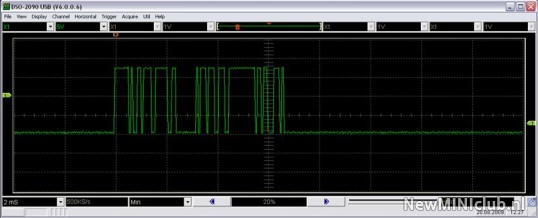
I couldn�t get the Arduino serial input reading the signal from pin 9 of the (Reslers module) Max232 as you described in one of your first posts. For this reason I read all the codes from the steering wheel buttons (in us) and wrote some code for the Arduino to recognize them. This works fine except when there is a lot of traffic on the IBus. During driving, one out of ten times you have to press a button twice. For this reason I will give it another try to get the serial communication working. Can you post a picture how you did this?
Nevertheless, the first version is installed and running
Hm...actually, for the Serial Input, the levels are supposed to be TTL, so when IBus is low, it should be 0-0.8V output to the Arduino, High should be close to +5V. I think then that transistor I was inverting with was unnecessary? Is the IBus -12 when low + 12 when high? Or is it 0 low, +12 high? If so, a simple resistor in the latter case to drop the voltage to +5V will work, not sure what it should be in the former case.
The IBus is 12V if there is no traffic and pulled low (0V) when transmitting. So you need to invert it and make it 0-5V. I did this with a transistor using the 5V out of the Arduino. This is the result for the volume down button:
I think you are saying that on the I-Bus, the idle state is high and the transition from high/+12V to low indicates the start bit and the rest of the bits are sent Low=0V, High=+12V? If this is correct, then I would have to write a custom software serial driver and not be able to use the UART built into the dedicated serial ports. DOH!!!
I couldn�t get the Arduino serial input reading the signal from pin 9 of the (Reslers module) Max232 as you described in one of your first posts. For this reason I read all the codes from the steering wheel buttons (in us) and wrote some code for the Arduino to recognize them. This works fine except when there is a lot of traffic on the IBus. During driving, one out of ten times you have to press a button twice. For this reason I will give it another try to get the serial communication working. Can you post a picture how you did this?
Nevertheless, the first version is installed and running

Neutral
Joined: Jan 2010
Posts: 1
Likes: 0
ibus message translation
Hi. Stumbled upon this thread looking for a way to translate ibus messges. Basically I have newer Bluetooth TCU in my BMW, and it doesn't understand the ibus message sent by my steering wheel for voice activation - when I send the correct message on the IBUS directly using Resler the unit responds properly. So...
I am looking to build a small translator box that looks for the "old" message and then transmits the new.
I was thinking a simple Arduino based circuit using a TH3122 would be the way to go.
In reading this thread it seems that people have had problems making this work. Did anyone ever get this to work?
My design would call for a simple voltage regulator to power the board, hook the ibus directly to the TH3122 and hook the TH3122 to the Arduino.
Using an Arduino Mini Pro might make this easier.
If I use just the chip, how can I program it ?
I am a experienced software engineer so coding the Arduino is no problem, but my EE skills haven't been tested since highschool....
Sorry for the late reply folks, been busy with other projects and this IBus project as fun as it is has been sort of been on the back burner for me.
For those interested in a more turn key solution (ie. not having to hack into the Resler's interface via cutting pins and soldering leads/hacking the board), I've been in contact with a manufacturer of IBus/K-Bus modules that use the Melixis chip, and he's interested in making something that may be of interest to some of you here (quoted prices are tentative/ballpark, not finalized yet):
This may be much easier for many of you to use, the boards are still in testing and I'll give you folks an update when I get a chance to play with one. Especially exciting is the very reasonable price on the Bluetooth one that will let you access the IBus data wirelessly (ie. via laptop or PDA/iPhone if someone writes an app for that).
Dave
For those interested in a more turn key solution (ie. not having to hack into the Resler's interface via cutting pins and soldering leads/hacking the board), I've been in contact with a manufacturer of IBus/K-Bus modules that use the Melixis chip, and he's interested in making something that may be of interest to some of you here (quoted prices are tentative/ballpark, not finalized yet):
There will be three versions available:
1. For Ardunio-Projects ... this one will be for 29.99 + Shipping as it will not contain the USB or Bluetooth chips only the Melexis Chip.
2. For the USB version 39.99 + Shipping
3. For the Bluetooth 59.99 + Shipping
You'd be able to hook on the SEN, RX & TX signals using the through holes. There will be no need to cut signals, as I added bridges (see them in layout/schema J1, J2, J3, J4) these are solder jumbers that you can connect or disconnect wires by just a point solder.
Dave
Robert,
This is the way I've been able to interface the Arduino with Resler's IBus interface, check earlier posts for schematics and hacking/hookup information.
I had a previous design using the TH3122 reference design circuit that I never did get working properly, not sure what is the matter but it didn't read the IBUS signal as I'd implemented it thus I had to keep using the Resler's interface.
I've posted some Arduino code in some earlier posts, feel free to use this code and modify to your needs. More information can be found at:
www.arduino.cc
The programming code is very similar to C and quite straight forward.
Good luck,
Dave
Hi. Stumbled upon this thread looking for a way to translate ibus messges. Basically I have newer Bluetooth TCU in my BMW, and it doesn't understand the ibus message sent by my steering wheel for voice activation - when I send the correct message on the IBUS directly using Resler the unit responds properly. So...
I am looking to build a small translator box that looks for the "old" message and then transmits the new.
I was thinking a simple Arduino based circuit using a TH3122 would be the way to go.
In reading this thread it seems that people have had problems making this work. Did anyone ever get this to work?
My design would call for a simple voltage regulator to power the board, hook the ibus directly to the TH3122 and hook the TH3122 to the Arduino.
Using an Arduino Mini Pro might make this easier.
If I use just the chip, how can I program it ?
I am a experienced software engineer so coding the Arduino is no problem, but my EE skills haven't been tested since highschool....
I am looking to build a small translator box that looks for the "old" message and then transmits the new.
I was thinking a simple Arduino based circuit using a TH3122 would be the way to go.
In reading this thread it seems that people have had problems making this work. Did anyone ever get this to work?
My design would call for a simple voltage regulator to power the board, hook the ibus directly to the TH3122 and hook the TH3122 to the Arduino.
Using an Arduino Mini Pro might make this easier.
If I use just the chip, how can I program it ?
I am a experienced software engineer so coding the Arduino is no problem, but my EE skills haven't been tested since highschool....
Any Interest in a Turnkey I-Bus/Arduino solution?
Hi folks,
Since I've had no success at creating my own Melixis/Arduino interface to do away with my ugly little hardware hack of the Reslers interface, I've been in touch with the guys at eedesignkits.com about some I-Bus products that they've been developing and testing.
They will be coming out with a very nice USB I-Bus interface that will be easily hackable (easy to solder pin outs for interfacing to a serial device like the Arduino or other microprocessor/PIC/Basic Stamp device) and easier to get/modify than the Reslers interface.
They are also making a Bluetooth I-Bus interface which would be really cool for logging I-Bus codes from a laptop or interfacing with a car PC.
Both interfaces are I-Bus powered/Car 12V powered so no external power is needed.
They are also considering making a all in one I-Bus (Melixis surface mount chip interface circuit) to Arduino interface for those of you who want to minimize your hassle/trial-and-error in getting into accessing the I-Bus in your MINI or BMW (pre 2006 MINI and earlier BMW's that have an I-Bus instead of the newer CAN bus, pre 2004?).
Starting a second dedicated thread on this here:
https://www.northamericanmotoring.co...interface.html
Check over there and post if you might be interested in such a product, what features you'd want (included Arduino, having it as an add on shield to an existing Arduino, if you'd want pre-installed/wired components like relays, switches, lights/LED's, LCD Interface, sound interface/speaker/buzzer, or whatever else you'd find interesting). This would be an ideal solution for those of you who want to get into this but don't feel comfortable or have the time/$$/expertise to design an entire circuit/board from scratch.
Dave
Last edited by DaveC; Mar 20, 2010 at 04:17 PM.

Neutral
Joined: Jun 2011
Posts: 1
Likes: 0
I Bus command HK minicooper amplifier
Just been reading your article re I/ K Bus on the mini cooper Not being to ofay with the IBus although I have some knowledge gained from reading extracts on the Ibus via to your references to other articles
I have the same problem and need to interface a Pic micro to the K-Bus Interface IC marked as Elmos 10020B
I see there is some type of serial port connector on the PCB which seems to link into the K-Bus IC
I have already gained proficient knowledge to be able to write my own software, however my difficulty is with the relative commands that need to be sent to the peripheral chip , so as to switch the amplifier on, adjust volume, balance etc
Could you send me a list of these commands in hex together with a possible example of what response i should receive and also the size of the packet
Could you also advise what address i should be sending these to with some initial steps
I have also experience in java ,C, basic , and assembler but plan to make a complete sofwtare package at some stage to achieve this and more
Any help greatly appreciated
Nice article by the way
Mark Harrington "newbie "


6th Gear
Joined: Jan 2005
Posts: 1,231
Likes: 0
From: RVA
I'd completely forgotten about this thread (as has just about everyone else, it would seem! ). Earlier this year I got a working IBus device that presents an iPod or iPhone to the head unit as a Sirius satellite radio receiver. The code is based on the Arduino libraries, but I had to do some hacking of the core code to provide closer access to the serial hardware. I designed and built a board that came out quite nicely. I use it in my MINI and also in my '91 BMW (which has a head unit from an '06 R53, which was really why I started the project). The code and schematics are up on GitHub.
). Earlier this year I got a working IBus device that presents an iPod or iPhone to the head unit as a Sirius satellite radio receiver. The code is based on the Arduino libraries, but I had to do some hacking of the core code to provide closer access to the serial hardware. I designed and built a board that came out quite nicely. I use it in my MINI and also in my '91 BMW (which has a head unit from an '06 R53, which was really why I started the project). The code and schematics are up on GitHub.
4th Gear
Joined: Mar 2006
Posts: 459
Likes: 6
From: Renton, Washington
I would love to have my R/T button activate the Headlight washer pump. I removed my rear wiper & painted my headlight rings a long time ago. I disconnected the sprayers to avoid chipping the paint on the headlight rings so I want to hook-up the unused washer pump to an intercooler sprayer activated by the "Road/Track" button ; )
The original hacked together electronics I made with the Resler RS232 board worked for me, but was pretty ugly/fragile.
I just found and ordered one of these:
http://www.ebay.com/itm/BMW-IBUS-I-B...item2558a623fe
I'm going to give it another try and interface it with one of these:
http://www.kickstarter.com/projects/...-usb-dev-board
Not sure if the IBus/USB interface will provide power to the USB Port to power the Digispark, but it'd be easy to draw power off the +12V line to do that if it doesn't.
Should make a tiny little package when plugged directly into the $30 IBus/USB interface. Should be fairly easy to design. You'll have 4 outputs from the Digispark at your disposal to control a relay (schematic included below). The Digispark is small and if you solder on some header pins, you should be able to use a small prototype board to build your relays, connections, etc onto.
The iBus codes for the buttons on a 3 spoke steering wheel are as follows (I think, check this by hooking up the IBus/USB interface to a computer and use a serial comm program to read the codes to verify):
Vol Up 80 4 104 50 17 31
Vol Down 80 4 104 50 16 30
-> Down 80 4 104 59 1 6
-> Up 80 4 104 59 33 38
-> Hold 80 4 104 59 17 22
<- Down 80 4 104 59 8 15
<- Up 80 4 104 59 40 47
<- Hold 80 4 104 59 24 31
R/T 80 3 -56 1 -102
Tel Down 80 4 -56 59 -128 39
Tel Up 80 4 -56 59 -96 7
Tel Hold 80 4 -56 59 -112 55
These are in Decimal, the hex codes are documented in the .PDF attached.
Hope this helps,
Dave


Neutral
Joined: Apr 2016
Posts: 1
Likes: 0
Where to Begin
I recently bought a 2004 Mini Cooper and I am interested in tinkering with it a bit. The thing is I only have minimal experience programming (non with Arduino or C) and circuitry. So I guess I am wondering where I should begin with all of this? I've been trying to find resources about CAN and networks within cars but they don't dumb it down enough for me haha.

R50
I recently bought a 2004 Mini Cooper and I am interested in tinkering with it a bit. The thing is I only have minimal experience programming (non with Arduino or C) and circuitry. So I guess I am wondering where I should begin with all of this? I've been trying to find resources about CAN and networks within cars but they don't dumb it down enough for me haha.
http://new.minimania.com/articlelist...%20Information
If you have a specific electrical or circuitry question, please ask and I'll pass along to our resident expert


6th Gear - NAM Hall of Fame
Joined: Apr 2017
Posts: 3,967
Likes: 393
From: soggy pnw
Interesting thread. Subscribed.
My 05 MCS has MFSW. When new I installed Mini Disc HU and a 6 Mini Disc changer and were able to preserve the audio control of the MFSW. Now in the mobile age I replaced the Sony Mini Disc system with an Alpine with BT and hands free smart phone support. It, as most after market HUs now don't have the MFSW interface capability. The truth is, I don't miss the capability, as they are so limited. The Alpine HU sounds infinitely better than the Sony it replaced.
I may want to play with adapting the audio controls of the MFSW for other uses - like firing a phaser to vaporize the distracted driver in front of me.

Thread
Thread Starter
Forum
Replies
Last Post
Interior/Exterior Unboxing Video of Sneed4Speed R53 Brake Cooling Kit
Gremothra
Interior/Exterior
3
Sep 9, 2015 08:42 PM