When you click on links to various merchants on this site and make a purchase, this can result in this site earning a commission. Affiliate programs and affiliations include, but are not limited to, the eBay Partner Network.
This is a great project and I�m hoping it�ll eventually lead to another affordable mod for my car.
I can�t help with any technical info, but if anyone here on NAM knows about these engines and why things were, or might have been, designed a certain way, it would be Unbreakable Lump as he was the lead engineer of the development team for these motors.
With the cams and headers that we have now as well as pulleys to provide more boost, would think anything that can assist in air being brought into the system more efficiently is going to be a plus.
So yesterday I did a bit of logging in order to see some very basic data. I used two cars for the logging. Both cars were logged the same time.
I though it will be a nice comparison as the two cars are so closed spec wise, with a small advantage on car 2. Both cars had 100 RON fuel, nearly same mileage, extremely well maintained.
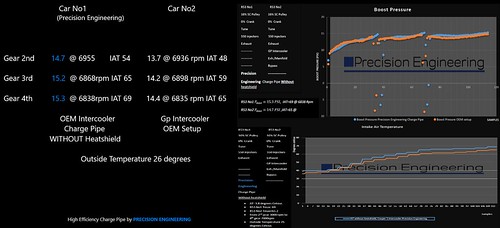
Car No1 specs (that's my car) : Car No2 specs:
16% sc pulley 16% sc pulley
0% Crank pulley 0% Crank pulley
Exhaust (back box only) Exhaust ( Mynes Header, 200 cell catalytic converter and back box)
Bytetronik Tune Bytetronik Tune
550 Injectors 550 Injectors
Charge Pipewithout heatshield GP Intercooler
After market Bypass
OEM intake
Outside Temperature 26 degrees at 2 am !! It is very hot here !
Below you can see some graphs from the measurements. What you will realise is that car No1 produce more psi although is operating with increased IAT compare to car No2. To be honest I do not remember my car producing 15+ psi of boost with that heat. I could only see numbers above 15 only during the winter. I will need some time before the heatshield is going to be ready. When it will be done I will do exactly the same measurements with the heatshield on. Just keep in mind that I have not finished the data collection, I am aware that there are many things to be done. So far I am very happy with how it performs! Please guys give me your thoughts - opinions.
it's all absolutely worthless data comparing 2 cars with a new product vs old..............YOU MUST HAVE CONTROL DELTA's
hate to be a pain but this testing is useless unless in a controlled environment on the same car
no you are not a pain at all !! actually thank you for the comment. It's not the only test I will do. To be honest I wanted to be sure that it performs ok.
I found a dyno that I will book to do back to back pulls with the same car, so I can have solid data concerning the delta factor.
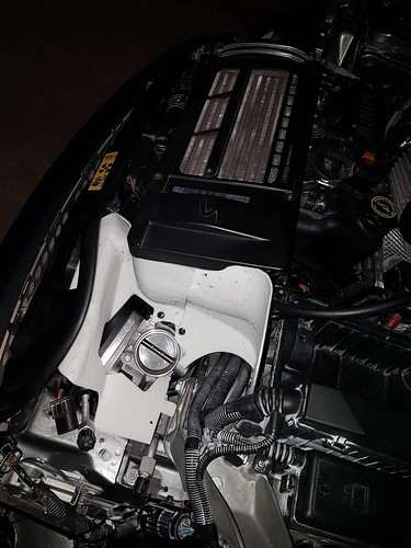
So I have a printed version of the heatshield but as I said I had a small problem. Well when I did the 3d scan I had the previous charge pipe version installed ( I know rookie mistake !! ) thus my fix points were a bit off. The engine bay of course remains the same but the position of the charge pipe is different. Thus I will do a new 3d scan this week and redesign the heatshield. In the pictures you see below the carbon fiber prototype is installed, that's why you see a gap around the throttle body. I think you can understand how it will look like later. In the next version everything will be in the correct position.
P.S I had to trim a bit of material, close to ECU. (when it will be in the correct position it will be ok)
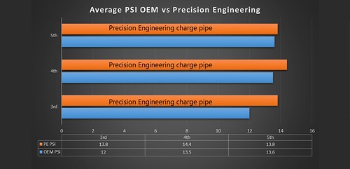
So I found some old logs of my car with same spec, outside temperature, fuel, driver etc and I compared them against the latest logs of the car. I could see through out the rev rage an increase in the boost level although the increased IAT (new logs are with the charge pipe but without the heatshield).
So I made a chart with the average boost level in each gear comparing the two logs. The results so far verify the feeling the car gives me , so I am very happy !!
Next steps:
New 3D scan of the engine in two days, redesign of the heatshield, print a 3d model.
Make another prototype in order to be installed in a friends car, so he can drive with it for a while and give me feedback.
Book a dyno, do back to back pulls.
By the way what do you think of the heatshield I posted in the previous post? Do you like it ?
I would tend to agree with pnwR53's comment #1, post #11.
While not for the reason he states, because in my opinion, NOT, because of the blowers rotor design, rotor quantity, pull, air flow vacuum in general, but for any round container that has a gas and or solid (air OR air-fuel) in general, will tend to swirl. Just a matter of simple physics.
I wont pretend to second guess why the Mini designers made that tube in the "shapes" that they did, but as long as the cross-section square inches (American values!) slightly exceeds the throttle body's square inches, it can any shape it wants. Again, as long as there are no excessive pinch points.
If I were doing this, I'd rather see a shape that discourages anything but a straight, full flow with no airflow rotation/swirl, and no small radius corners that will have low flow areas.
Maybe a round tube (slightly larger than the throttle body diameter) would work well with something like vortex generators in the id of the tube. This would eliminate low flow areas, keep any swirl away, help make the entire cross section of the tube flow nearly the same amount of air, rather than fast in the center and slower nearer the walls (again, physics 101).
P.E - At least you are working to better the output of the little engine.
Nearly done with the new design of the heatshield. Some minor modifications and then I will print and test fit it.
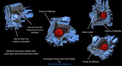
The last days I am playing with an idea... I want the outer layer of the heat shield to be made from aluminium fiber and the inner from carbon fiber. So outer layer is the layer that we can not see (faces the ground and the intercooler horn). I want to make two prototypes one with the aluminium skin and one without and see if there is any difference with the temperatures.
More updates:
The billet air-filter adapter should be ready next week.
by https://www.flickr.com/photos/141887782@N03/, on Flickr
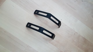
And I also did some brackets but I have not fitted yet to see if everything is ok. Again I am thinking to use carbon fiber for the brackets, as I have done some to support an exhaust and the result was very nice.
This is fantastic mate. Another mod that can be added to compliment everything. Loving all the datail, and can't wait for the final results. So glad you havnt been discouraged at all either. Any idea on cost of your finished charge pipe kit when completed? Keep up the fantastic progress
It is hard to say a price now ! It is not even finished and I do not have a company yet, everything is in development stage for now. I had a discussion with a friend (MINI driver) about the charge pipe, as I told him it will be two products in one. The charge pipe (carbon charge pipe, throttle cable extention with OEM components, silicone hoses, brackets, instructions) plus the intake (carbon fiber heatshield, billet anodised adapter, airfilter, hoses, brackets) plug and play etc. Lets say that the cost of producing the kit is way more compared to the average intake kit (silicone hose, aitfilter, airbox ) that you could find up to now, but the material, RnD and effort are different as well.
Will be standing by final results and release. Will you be able to release just the charge pipe conversion kit without the whole air filter upgrade, as most probably already have air filter kits installed, or because of the new pipe you are forced to upgrade the air filter kit as well due to space etc
Will be standing by final results and release. Will you be able to release just the charge pipe conversion kit without the whole air filter upgrade, as most probably already have air filter kits installed, or because of the new pipe you are forced to upgrade the air filter kit as well due to space etc
Yes I want to give the option for selecting only the charge pipe, it could be exactly as it is now in my car (prototype), only the charge pipe, brackets, cable extension, billet adapter airfilter and all the support components needed or just the charge pipe. That can reduce the cost a lot!
More updates:
I designed a JIg to ensure plug and play fitment every time without having to test it on my car . The whole JIG it will be printed in the next weeks.
(the new version of the heatshield is being printed as we speak) Charge pipe JIG
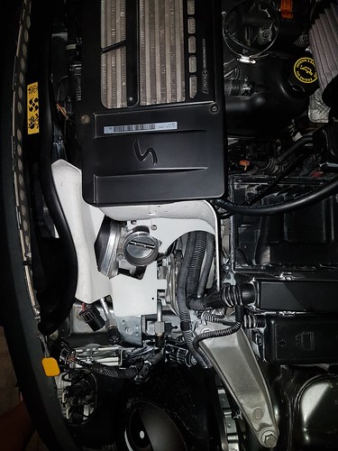
So today I put the billet adapter on the car. I took some photos so you can see how it looks with the air filter on.
Keep in mind that the adapter is not anodised, just raw aluminium. I want to anodised them mainly to protect them from corrosion. You will notice that there is a small aluminium tube comming out of the top of the air filter. This is the return line from the PCV valve. Billet adapter, PCV adapter and high flow air filter. Tapered design, enlarged filter diameter, no step in the geometry.
Hello guys, at last I have some proper updates. The new printed model of the heat shield is ready. I am so happy with it as it fits perfectly as it should be.
Excuse the blue duct tape ! I had to print the model in parts and I run out of glue. I will do some testing with the printed model and then I will make a carbon fiber prototype for proper testing. Good news I got another job (3 so far ) spending more for RnD now it will be easier. So after the carbon fiber prototype is ready, Dyno and more testing. What do you think? any comments are welcome.
Thank you all of you for the kind words!
I haven't update the topic for a while (because the extra new job consumes a lot of my time and during August everyone is on holidays here!). So far I have done a bit more than 2000km with the charge pipe on and around 500km with the printed heatshield. I use the car in daily bases in order to go to my job.
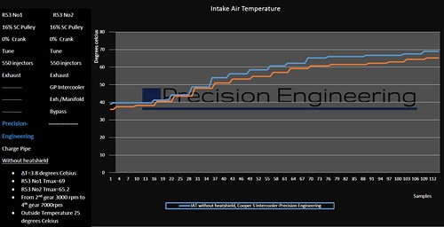
Previous weekend I removed everything and inspected the kit. I am happy to report everything looks as it should be without any marks from touching or hitting the radiator or other components . Yesterday I did a log with the heat shield. It feels like the car pulls better, the IATs seem to be lower (expected), even with aircon, 38 degrees outside temperature (around 4pm) the cars pulls so nicely compare with the OEM setup.
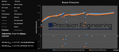
The log I did was early in the morning, 6:30 am with 27 outside temperature ! All the logs I use for comparison reasons have been done with the same outside temperature. Below you can see the graphs with the charge pipe kit (with the heat shield) vs the oem setup.
What do you think guys? To be honest first time I see 16 psi during summer in Greece !! Even during the winter I could see maximum 15 to 15.3 psi ! I really want to dyno it but with these temperatures I prefer to wait a bit!
Charge Pipe kit with Printed heat shield (for testing reasons) VS OEM setup
I leave on the other side of the mountain Penteli, I could see and smell the smoke. Terrible disaster.
Two days later the side I am leaving flowed by the rain ! Irony I know.
 06-30-2018, 04:08 AM


 ) spending more for RnD now it will be easier. So after the carbon fiber prototype is ready, Dyno and more testing. What do you think? any comments are welcome.


 . Yesterday I did a log with the heat shield. It feels like the car pulls better, the IATs seem to be lower (expected), even with aircon, 38 degrees outside temperature (around 4pm) the cars pulls so nicely compare with the OEM setup.
  ! All the logs I use for comparison reasons have been done with the same outside temperature. Below you can see the graphs with the charge pipe kit (with the heat shield) vs the oem setup.