Solution to oil consumption, vlv cover leak and more?
#1
 04-08-2012, 02:44 AM

Is this the "Solution" to oil consumption, vlv cover leak and more?
On turbo cars, there is a Crankcase breather system. In the valve cover lives a diaphragm valve that if leaks will cause full intake vacuum (or pressure?) to be applied to the crankase,resulting in excessive oil consumption, irreguler idle, or oilly smoke in the exhuast.
From the Bentley manual page 130-54.
From the Bentley manual page 130-54.
Last edited by JPMM; 04-08-2012 at 04:22 AM.
The following users liked this post:
930 Engineering (08-06-2021)
#2
04-09-2012, 05:01 AM

#3
04-09-2012, 05:33 AM


#7
04-09-2012, 10:56 PM

No official test in the Bentley Service Manual.
"The internal crankcase ventilation system is integrated into the plastic cylinder head (valve) cover. The crankcase breather valve is part of the cylinder head (valve) cover and is NOT serviceable as a separate component. ...The pressure control valve varies the vacuum applied to the crankcase breather depending on engine load. The valve is balanced between spring pressure and the amount of manifold vacuum..."
- Erik
The following users liked this post:
930 Engineering (08-06-2021)
Trending Topics
#8
04-10-2012, 04:22 AM
#9
04-10-2012, 05:35 AM
Hi It gives specs in the manual,
control valve
opens when pressure is less than 30mbar
and closes when pressure is greater than 30 mbar,
so test to those parameters'
A faulty crankcase breather valve causes significant deviations from the specified value:
Crankcase venntilation clogged: Ambient pressure+ 100mbar
Crankcase ventilation internal leak: ammbient pressure-170mbar.
Not sure what it all means, but there you all go
No official test in the Bentley Service Manual.
"The internal crankcase ventilation system is integrated into the plastic cylinder head (valve) cover. The crankcase breather valve is part of the cylinder head (valve) cover and is NOT serviceable as a separate component. ...The pressure control valve varies the vacuum applied to the crankcase breather depending on engine load. The valve is balanced between spring pressure and the amount of manifold vacuum..."
- Erik
"The internal crankcase ventilation system is integrated into the plastic cylinder head (valve) cover. The crankcase breather valve is part of the cylinder head (valve) cover and is NOT serviceable as a separate component. ...The pressure control valve varies the vacuum applied to the crankcase breather depending on engine load. The valve is balanced between spring pressure and the amount of manifold vacuum..."
- Erik
The following users liked this post:
930 Engineering (08-06-2021)
#10
06-06-2012, 11:40 AM

#11
06-12-2012, 04:42 AM
#12
06-24-2012, 12:29 AM

4th Gear
I'm exploring this right now
My valve cover's off, as I'm replacing a burned exhaust valve at 90k. My intake valves were ridiculously caked with carbon, BTW.
I'm rerouting by plugging the PCV to the throttle body (rear PCV, pass. side) with BSH Dual Boost Tap (closed) and adding the BSH catch can to the turbo inlet PCV (driver side).
My scientific valve cover smooching has proven, When you blow on the rear PCV port on the valve cover it closes, suck and it opens. There is seemingly no progression to the suck/open state. This design prevents high pressure boost from pressurizing you crankcase. Do the same with the side PCV port on the valve cover, and there is no valve closing effect. This is because in off-boost condition, PCV pulls fresh air from just before turbo inlet into the crankcase, and removes it through the rear, due to stronger vacuum in manifold. When you transition to boost, the rear port closes, and the side port sucks air from the crankcase.
If the rear valve fails and boost pressure enters you crankcase, it could turn the side port into a stream of pressurized crankcase vapor, thus burning oil more quickly, and also leading to seal failures. As far as I can tell, there is no side port valve to fail.
I'm a little surprised that the inlet and outlet when both ports are open, is into the same area above the valve train. That design wouldn't seem to encourage exchange of all the crankcase vapors.
#13
06-25-2012, 05:46 AM

My valve cover's off, as I'm replacing a burned exhaust valve at 90k. My intake valves were ridiculously caked with carbon, BTW.
I'm rerouting by plugging the PCV to the throttle body (rear PCV, pass. side) with BSH Dual Boost Tap (closed) and adding the BSH catch can to the turbo inlet PCV (driver side).
My scientific valve cover smooching has proven, When you blow on the rear PCV port on the valve cover it closes, suck and it opens. There is seemingly no progression to the suck/open state. This design prevents high pressure boost from pressurizing you crankcase. Do the same with the side PCV port on the valve cover, and there is no valve closing effect. This is because in off-boost condition, PCV pulls fresh air from just before turbo inlet into the crankcase, and removes it through the rear, due to stronger vacuum in manifold. When you transition to boost, the rear port closes, and the side port sucks air from the crankcase.
If the rear valve fails and boost pressure enters you crankcase, it could turn the side port into a stream of pressurized crankcase vapor, thus burning oil more quickly, and also leading to seal failures. As far as I can tell, there is no side port valve to fail.
I'm a little surprised that the inlet and outlet when both ports are open, is into the same area above the valve train. That design wouldn't seem to encourage exchange of all the crankcase vapors.
I'm rerouting by plugging the PCV to the throttle body (rear PCV, pass. side) with BSH Dual Boost Tap (closed) and adding the BSH catch can to the turbo inlet PCV (driver side).
My scientific valve cover smooching has proven, When you blow on the rear PCV port on the valve cover it closes, suck and it opens. There is seemingly no progression to the suck/open state. This design prevents high pressure boost from pressurizing you crankcase. Do the same with the side PCV port on the valve cover, and there is no valve closing effect. This is because in off-boost condition, PCV pulls fresh air from just before turbo inlet into the crankcase, and removes it through the rear, due to stronger vacuum in manifold. When you transition to boost, the rear port closes, and the side port sucks air from the crankcase.
If the rear valve fails and boost pressure enters you crankcase, it could turn the side port into a stream of pressurized crankcase vapor, thus burning oil more quickly, and also leading to seal failures. As far as I can tell, there is no side port valve to fail.
I'm a little surprised that the inlet and outlet when both ports are open, is into the same area above the valve train. That design wouldn't seem to encourage exchange of all the crankcase vapors.
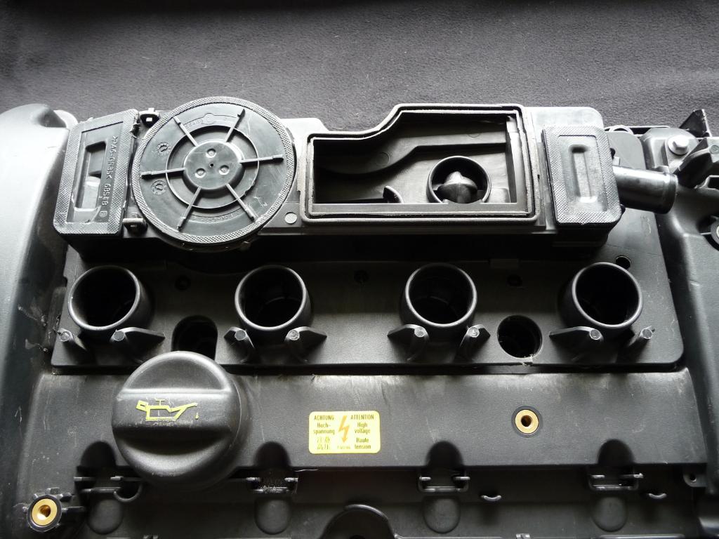
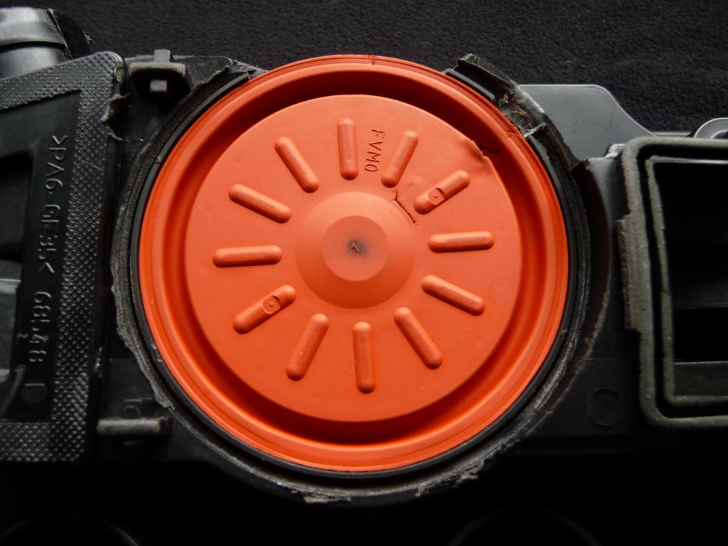
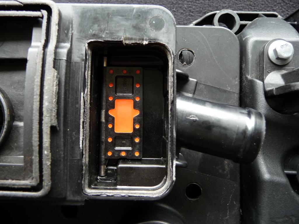
Here is the cam cover showing the various sections, and the PC valve flap diaphragm's.
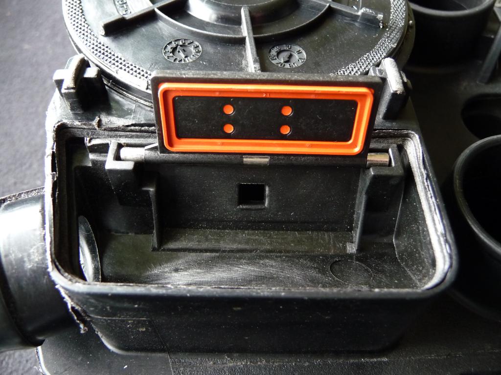
Rear PC valve flap diaphragm in it's natural closed positions.
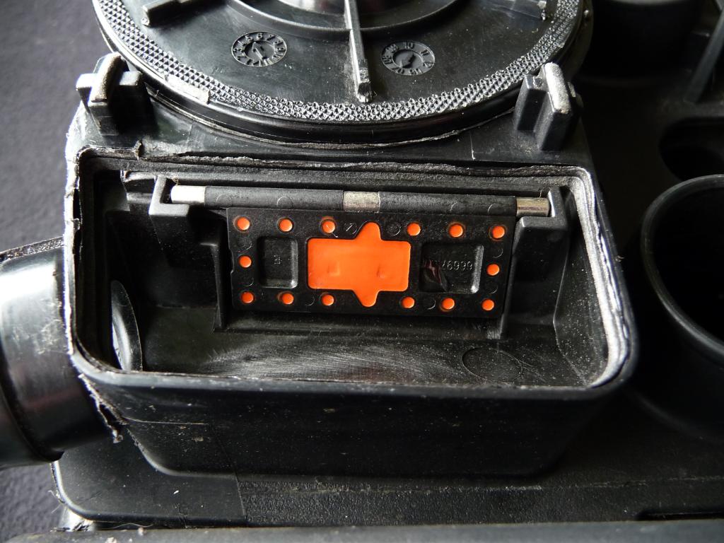
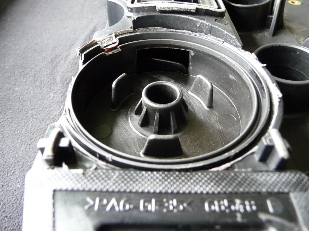
Rear PC valve flap diaphragm, open (this open position is vastly exaggerated, and will not be like this with it's lid on) showing the port passage exit.
Central sprung pressured diverter.
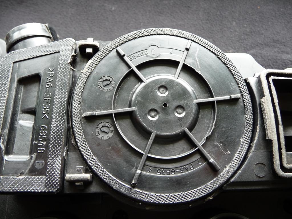
Diverter diaphragm (ignore the damage)
Underside of Diaphragm and pressure control spring.
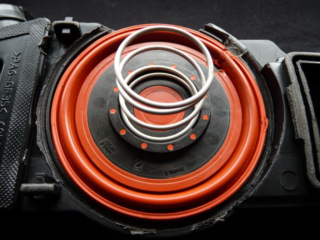
Diaphragm direction/pressure control valley.
Central valley separation step
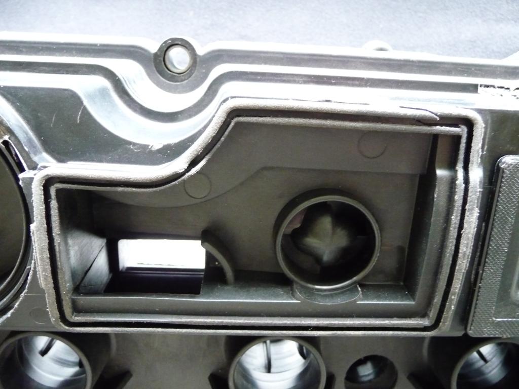
Right hand side, PC valve diaphragm flap, in it's natural closed position.
Valve diaphragm flap open, showing the port passage exit.
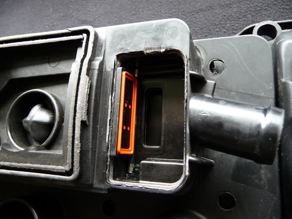
Hopefully this should help explain the PCV system, that said the very latest cam cover for the N14 engine, has some slight revisions, to the oil mist guide and entrapment valley's, and the PC valve diaphragms are cylindrical free falling, as apposed to the oblong valve diaphragm flaps, in my images.
The following users liked this post:
930 Engineering (08-06-2021)
#14
06-25-2012, 06:58 AM
I'm assuming based on those pictures, these moving parts in the valve cover are NOT servicable and you had to cut this valve cover open to gain access?? It looks as if they are pressure melted together (my technical term!!).
If that diaphram ruptures (as shown) or the flaps become fouled, the complete valve cover needs to be replaced. Too much waste. I hate that type of engineering.
If that diaphram ruptures (as shown) or the flaps become fouled, the complete valve cover needs to be replaced. Too much waste. I hate that type of engineering.
#15
06-25-2012, 07:12 AM
I'm assuming based on those pictures, these moving parts in the valve cover are NOT serviceable. Correct. and you had to cut this valve cover open to gain access?? Yes. It looks as if they are pressure melted together (my technical term!!).
If that diaphram ruptures (as shown) It was damaged by me. or the flaps become fouled, the complete valve cover needs to be replaced. Not necessarily you could wash it out. Too much waste. I hate that type of engineering.
If that diaphram ruptures (as shown) It was damaged by me. or the flaps become fouled, the complete valve cover needs to be replaced. Not necessarily you could wash it out. Too much waste. I hate that type of engineering.
#16
06-26-2012, 09:55 AM

#17
06-26-2012, 03:49 PM
This is now a concerning time, as you expect the manufacturing dealer to be competent when working on your car, however, the manufacture dealer, reads the forums, chats and blogs, I order to find answers, how concerning is that ?
I may not be able to stop this madness, but I can try to educate the masses with supplying correct information, on the many forums, chats and blogs, I contribute to, and the various Motorsport/Automotive industry platforms I am involved with, even at such high levels, there is much blinkered stupidity, like you wouldn't believe, Ive walked out of many a meeting and often do, laughing and shaking my head, at the unbelievable lack of basic engineering all thanks to this marvellous revolution in computerised controlled diagnostics, apparently if there is no fault code, there is not fault!

#18
06-26-2012, 04:04 PM
important information
nice job with the photos, so is the failure of the these valves the smoking gun with respect to oil consumption and intake valve fouling
Thank you so much for your kind appreciation Mike, there is so much misguided technical information throughout the automotive forum/blog chat world, that the automotive enthusiast believes what they read, from unknowledgeable jack of all trades, and master of none, internet guru's, and sadly this filters through to the dealer networks, as most of the dealer (so called technicians) read and blend what they read from the misguided automotive forum, chat blogs, into their computerised no logical thought process working schedule, to determine a fault.
This is now a concerning time, as you expect the manufacturing dealer to be competent when working on your car, however, the manufacture dealer, reads the forums, chats and blogs, I order to find answers, how concerning is that ?
I may not be able to stop this madness, but I can try to educate the masses with supplying correct information, on the many forums, chats and blogs, I contribute to, and the various Motorsport/Automotive industry platforms I am involved with, even at such high levels, there is much blinkered stupidity, like you wouldn't believe, Ive walked out of many a meeting and often do, laughing and shaking my head, at the unbelievable lack of basic engineering all thanks to this marvellous revolution in computerised controlled diagnostics, apparently if there is no fault code, there is not fault!
#19
06-26-2012, 04:50 PM
The very latest cam cover for the N14 engine, has had a PCV redesign, and incorporates vertical cylindrical diaphragm valves, which are pressure weighted, providing better directional flow control under vacuum/pressure conditions, providing the internal arterial entrapment separation valleys, steps, and troughs, are more efficient, this should reduce oil consumption and slow down the carbon deposit, to the backs of the inlet valves.
#21
06-26-2012, 05:03 PM

So it's not serviceable, as in taking it apart and replacing diaphragms and springs and such, but is it at least cleanable? If say, you had a parts washer tank with solvent in it, could you at least rinse the gook out so that it could move freely again?
Do you see the gooky condition on cars that have more frequent oil changes, or is it a condition brought on by constant stop/go short haul driving conditions?
Are there any contributing factors under the owners control?
Do you see the gooky condition on cars that have more frequent oil changes, or is it a condition brought on by constant stop/go short haul driving conditions?
Are there any contributing factors under the owners control?
#22
06-26-2012, 05:18 PM
Czar, would you have an approximate time when the updated valve cover was implemented with the updates you describe above? I know that they continue to use the N14 for JCW production. Can we assume that the later, improved cover would be able to be installed on an earlier motor?
Also, is it a reasonable conclusion that if your engine has shown carbon fouling of the intake, that there is likely some accumulation of gum on the valve seating surfaces? Or is there a way to inspect short of removing the valve cover?
Thanks,
Mike
Also, is it a reasonable conclusion that if your engine has shown carbon fouling of the intake, that there is likely some accumulation of gum on the valve seating surfaces? Or is there a way to inspect short of removing the valve cover?
Thanks,
Mike
#23
06-26-2012, 06:20 PM

5th Gear
Join Date: Sep 2009
Location: Tallahassee, FL
Posts: 719
Likes: 0
Received 0 Likes
on
0 Posts
#24
07-05-2012, 04:42 PM

2nd Gear
The common problem with this particular diaphragm valve flap arrangement, is the susceptibility to oil mist coagulation (gumming up) the oil particle separation ability of the entrapment passages, valleys and steps, is as best, poor, the unweighted free moving diaphragm valve flaps, controlling the directional oil mist vapour flow, suffers from heavy coagulation (gumming up) from the poor internal arterial entrapment passages within the cam covers PCV system.
The very latest cam cover for the N14 engine, has had a PCV redesign, and incorporates vertical cylindrical diaphragm valves, which are pressure weighted, providing better directional flow control under vacuum/pressure conditions, providing the internal arterial entrapment separation valleys, steps, and troughs, are more efficient, this should reduce oil consumption and slow down the carbon deposit, to the backs of the inlet valves.
The very latest cam cover for the N14 engine, has had a PCV redesign, and incorporates vertical cylindrical diaphragm valves, which are pressure weighted, providing better directional flow control under vacuum/pressure conditions, providing the internal arterial entrapment separation valleys, steps, and troughs, are more efficient, this should reduce oil consumption and slow down the carbon deposit, to the backs of the inlet valves.
Thanks for posting the pics, they are very informative.