How To Interior/Exterior :: Outmotoring Bonnet Brackets & Driving Lights
#1
 01-23-2007, 10:10 AM

Interior/Exterior :: Outmotoring Bonnet Brackets & Driving Lights
I'm putting this up because many people out there have asked me about the installation process of both the bonnet-mounted driving light brackets, as well as the installation/wiring of the lamps themselves. Hope this helps!
Installing The Outmotoring Bonnet Mounted Driving Light Brackets
Tools Required:
Drill w/ bit capable of drilling through metal
Phillips Head Screwdriver
Sharpie or marker with fine point
Drill punch or awl
Rivit gun (optional)
Stainless Steel metal screws (optional, but recommended)
Tape Measure
The bracket kit comes with pop rivets to affix the bracket to the car, however screws can be used if you do not have a rivet gun. In this installation, stainless steel metal screws that fit through the bracket mounting holes were used instead. If you decide to use screws, use stainless – they only cost a little bit more and they’re far more resistant to rust.
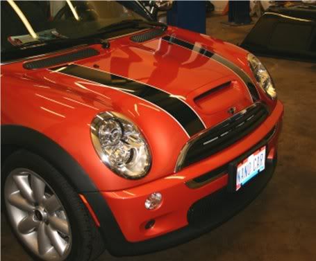
The test vehicle… the lights will sit at the end of the bonnet stripes on bonnet-mounted brackets.
Before mounting, open the bonnet and look on the inside, front surface of the bonnet. If there are two black plastic shields just forward of the bonnet blanket, covering the holes leading inside the bonnet, remove them with a screwdriver.
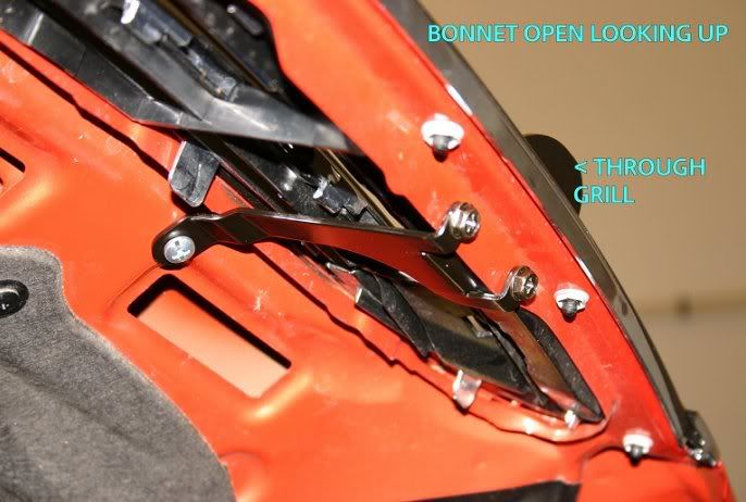
Test fit the brackets on the car. Note that the rounded, single-hole light mounting point actually goes through the grill slats, protruding forward past the grill (see last picture for the proper mounting configuration). There are two points where the bracket mounts to the car – the upper point has one hole and the lower has two. Once you have the brackets symmetrical (use a tape measure to check the distance from some symmetrical point, such as the grill fasteners), use the Sharpie or felt-tipped marker to mark your drill points.
Use the drill punch or awl to mark your drill point. This will give the drill bit a depressed hole to bite against.
Drill the holes for the screws. Start slow with a small bit to make a pilot hole, then use a larger bit to make the final hole. The drilled hole should be slightly smaller than the screw used for final mounting.
After marking the holes with a Sharpie or a felt-tip pen, use an awl or drill punch to start the hole, then drill. Start with a small pilot hole (as shown), then enlarge with a bigger bit. Don’t press hard or the drill bit might break or skate across the paint…
If you are using the supplied pop rivets, affix the brackets and use your rivet gun to secure the fasteners.
If using screws, mount the brackets and tighten all screws. LockTite or some other anti-vibration product is recommend, but not essential.
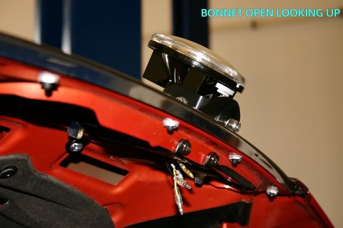
Final mounting position of the bracket. Note that the upper mounting point has one screw and the lower has two
Congratulations! You’re ready to mount your lights!
Mounting driving lights to bonnet-mount brackets.
Tools required:
Phillips-head Screwdriver
Wire strippers
Electrical Tape
Stainless steel bolts (2), Nylock nuts (2), split washers (4) and rubber washers (4 – optional).
Adjustable wrench or socket set.
Split-loom wiring insulation (optional)
Driving lights mounted to the bonnet will have their wiring pass through cut-outs in the underside of the bonnet and behind the bonnet blanket. This makes for a cleaner install, and protects the wiring from high temperatures and friction.
In planning your install, be aware of the following:
In most states, the law requires that the driving lamps be wired so that they only come on along with your high beams. This will require you to identify your high beam lamps’ power lead and tap into that wire, using a wire tap. You can also strip the wire carefully and splice in, wrapping the splice securely in electrical tape afterwards. The use of an independent switch to control the lights is not recommended, however most commercially available kits do include such a device – please see your lights’ installation instructions for device-specific limitations and special considerations. Note that the installation illustrated below shows lights that are wired direct to the battery using a supplied switch.
To begin, cover your cool-to-the-touch engine with a towel. This will keep you from dropping parts into the engine by accident.
Remove the NEGATIVE terminal from the battery (in the trunk, under the boot liner).
Lay out all your parts, including the lamps, the wiring harness, fuse and relay (if supplied). Make sure all the expected parts are included – there’s nothing worse than getting ¾ through an installation and realizing you’re missing a necessary part.
Check the manufacturer’s installation instructions for the recommended installation configuration. In out case, the lamps were Hella Optilux 2500 lights with “angel eyes” secondary lights. The lights connect direct to the battery and are driven by a 3-position independent switch. We decided to follow the manufacturer’s suggested installation, however we could have wired the lights into the high beams just as easily.
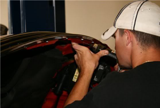
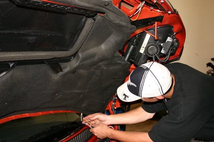
Unscrew the black plastic fasteners holding the bonnet blanket on the driver’s side, but do not remove the blanket entirely. This will allow for access behind the blanket.
Driver’s side driving light attached to bonnet bracket. The wiring harness will clip to the leads shown here, and will run into the rectangular cut-out just in front of the bonnet blanket. From there, the wires will run behind the bonnet blanket, which will protect them from heat and vibration
Attach the lights to the bonnet brackets, using the stainless steel bolts, lock washers and Nylock (anti-vibration) nuts. Rubber washers can also be used, if desired, to help minimize vibration. NOTE: many lights do not come with the hardware required to mount the lights to your brackets, but some do. If so, check the hardware carefully and replace the supplied bolts with stainless steel if they aren’t already made of this material. Traditional galvanized steel nuts and bolts will rust very quickly, resulting in an ugly install and hardware that’s difficult to de-install.
Connect the wring harness to the lamp(s). Run the wiring harness up into the space behind the bonnet (there are two large openings just aft of the point where the bonnet bracket mounts). Snake the wires through this opening and then between the bonnet blanket and the hood. You’re aiming to have the wires snake back to the driver’s side bonnet support.
If your lights came with a relay and/or a fuse, a perfect place to tuck these boxes is inside the bonnet itself – there are holes in the rear edge of the inside of the bonnet that are just large enough for extra wires and the relay box.
The lights’ wires are run behind the bonnet blanket, emerging near the driver’s side bonnet support. Be sure to run towards the driver’s side, as the firewall pass-through hole is on that side of the car. The relay and fuse are inside the bonnet itself, in a small cut out just above the mechanic’s hand, behind the blanket
If you are hooking direct to the battery, open the positive battery terminal cover and clip your positive power lead to the terminal. Run the wire up along the top of the air box shield. The rubber stripping at the top of the shield can be pulled up and the wire run along inside of it for the cleanest possible installation.
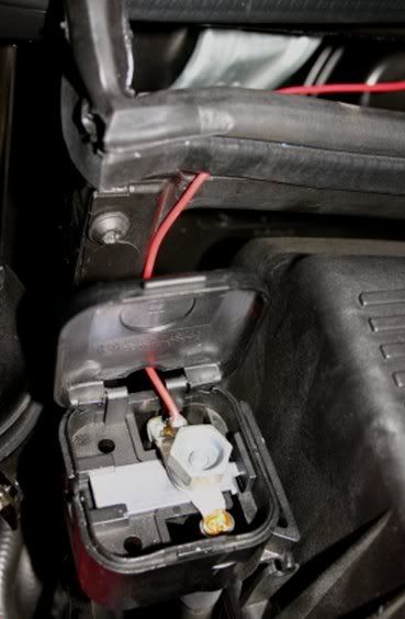
Positive wire, hooked to the battery terminal in the engine bay. The wire is threaded under the rubber gasket on the top of the air box shield – just pull it up, push the wire inside the rubber peice and replace
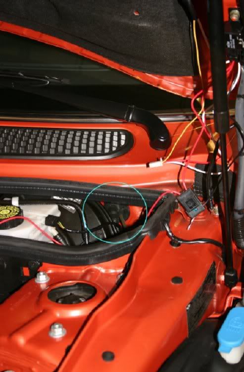
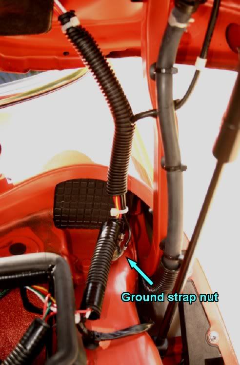
Zip-tie the wires leading from the lights to the existing ground strap wire on the driver’s side. Thread the wires through the wire pass-through on the driver’s side. Hook the power lead to the lamps. We covered the wires in split-loom protective covering material (available from Radio Shack) for additional protection and to create a cleaner look.
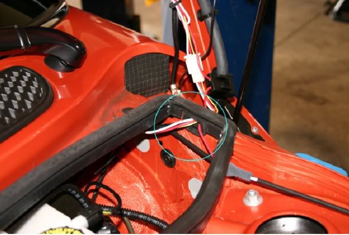
Illustration of the driver’s side wire pass-through. For reference, the black cable shown here running off the bottom left side of the picture is the bonnet release cable.
TEST THE LIGHTS with the supplied switch before running your switch wiring through the firewall. Re-attach the negative battery terminal and switch on the lights. If they do not illuminate, detach the negative terminal, then re-check all your connections and the fuse. Once you are sure everything is hooked up correctly and the lights are working, detach the negative terminal once again.
Re-attach the bonnet blanket, making sure that all your tucked wires are not crimped or rubbing against anything sharp.
Thread your switch wiring through the firewall. There is a rubber grommet on the driver’s side of the car, where the bonnet release cable and other wiring passes through from the cabin too the engine bay. There is plenty of extra room for more wires. The grommet may be covered by black tape – if so remove the tape first.
Here’s the firewall hole that you will pass your switch wires through. NOTE: if you are doing an installation with the driving lamps wired directly into your high beams, then you will not need a separate switch
To retrieve your wires, get in the car and pull down the driver’s side knee bolster (just give it a good yank and it will pull down), then look inside and UP towards the dash board. You’ll see your wires near the steering column.
Hook up your switch and mount it in the cabin (there are several possible locations, including the Euro-tray switch knock-out as well as the knockout on the center panel near the E-brake).
Re-attach the negative battery terminal. Replace knee bolster.
You’re done – congratulations!
This shot illustrates the best way to zip-tie the lamp wires to the existing ground-strap wire. The lamp wires emerge from beneath the bonnet blanket and run down towards the engine bay. The resulting bundle was then wrapped in plastic split-loom covering material to protect it from rubbing or crimping.
The finished product:

Installing The Outmotoring Bonnet Mounted Driving Light Brackets
Tools Required:
Drill w/ bit capable of drilling through metal
Phillips Head Screwdriver
Sharpie or marker with fine point
Drill punch or awl
Rivit gun (optional)
Stainless Steel metal screws (optional, but recommended)
Tape Measure
The bracket kit comes with pop rivets to affix the bracket to the car, however screws can be used if you do not have a rivet gun. In this installation, stainless steel metal screws that fit through the bracket mounting holes were used instead. If you decide to use screws, use stainless – they only cost a little bit more and they’re far more resistant to rust.
The test vehicle… the lights will sit at the end of the bonnet stripes on bonnet-mounted brackets.
Before mounting, open the bonnet and look on the inside, front surface of the bonnet. If there are two black plastic shields just forward of the bonnet blanket, covering the holes leading inside the bonnet, remove them with a screwdriver.
Test fit the brackets on the car. Note that the rounded, single-hole light mounting point actually goes through the grill slats, protruding forward past the grill (see last picture for the proper mounting configuration). There are two points where the bracket mounts to the car – the upper point has one hole and the lower has two. Once you have the brackets symmetrical (use a tape measure to check the distance from some symmetrical point, such as the grill fasteners), use the Sharpie or felt-tipped marker to mark your drill points.
Use the drill punch or awl to mark your drill point. This will give the drill bit a depressed hole to bite against.
Drill the holes for the screws. Start slow with a small bit to make a pilot hole, then use a larger bit to make the final hole. The drilled hole should be slightly smaller than the screw used for final mounting.
After marking the holes with a Sharpie or a felt-tip pen, use an awl or drill punch to start the hole, then drill. Start with a small pilot hole (as shown), then enlarge with a bigger bit. Don’t press hard or the drill bit might break or skate across the paint…
If you are using the supplied pop rivets, affix the brackets and use your rivet gun to secure the fasteners.
If using screws, mount the brackets and tighten all screws. LockTite or some other anti-vibration product is recommend, but not essential.
Final mounting position of the bracket. Note that the upper mounting point has one screw and the lower has two
Congratulations! You’re ready to mount your lights!
Mounting driving lights to bonnet-mount brackets.
Tools required:
Phillips-head Screwdriver
Wire strippers
Electrical Tape
Stainless steel bolts (2), Nylock nuts (2), split washers (4) and rubber washers (4 – optional).
Adjustable wrench or socket set.
Split-loom wiring insulation (optional)
Driving lights mounted to the bonnet will have their wiring pass through cut-outs in the underside of the bonnet and behind the bonnet blanket. This makes for a cleaner install, and protects the wiring from high temperatures and friction.
In planning your install, be aware of the following:
In most states, the law requires that the driving lamps be wired so that they only come on along with your high beams. This will require you to identify your high beam lamps’ power lead and tap into that wire, using a wire tap. You can also strip the wire carefully and splice in, wrapping the splice securely in electrical tape afterwards. The use of an independent switch to control the lights is not recommended, however most commercially available kits do include such a device – please see your lights’ installation instructions for device-specific limitations and special considerations. Note that the installation illustrated below shows lights that are wired direct to the battery using a supplied switch.
To begin, cover your cool-to-the-touch engine with a towel. This will keep you from dropping parts into the engine by accident.
Remove the NEGATIVE terminal from the battery (in the trunk, under the boot liner).
Lay out all your parts, including the lamps, the wiring harness, fuse and relay (if supplied). Make sure all the expected parts are included – there’s nothing worse than getting ¾ through an installation and realizing you’re missing a necessary part.
Check the manufacturer’s installation instructions for the recommended installation configuration. In out case, the lamps were Hella Optilux 2500 lights with “angel eyes” secondary lights. The lights connect direct to the battery and are driven by a 3-position independent switch. We decided to follow the manufacturer’s suggested installation, however we could have wired the lights into the high beams just as easily.
Unscrew the black plastic fasteners holding the bonnet blanket on the driver’s side, but do not remove the blanket entirely. This will allow for access behind the blanket.
Driver’s side driving light attached to bonnet bracket. The wiring harness will clip to the leads shown here, and will run into the rectangular cut-out just in front of the bonnet blanket. From there, the wires will run behind the bonnet blanket, which will protect them from heat and vibration
Attach the lights to the bonnet brackets, using the stainless steel bolts, lock washers and Nylock (anti-vibration) nuts. Rubber washers can also be used, if desired, to help minimize vibration. NOTE: many lights do not come with the hardware required to mount the lights to your brackets, but some do. If so, check the hardware carefully and replace the supplied bolts with stainless steel if they aren’t already made of this material. Traditional galvanized steel nuts and bolts will rust very quickly, resulting in an ugly install and hardware that’s difficult to de-install.
Connect the wring harness to the lamp(s). Run the wiring harness up into the space behind the bonnet (there are two large openings just aft of the point where the bonnet bracket mounts). Snake the wires through this opening and then between the bonnet blanket and the hood. You’re aiming to have the wires snake back to the driver’s side bonnet support.
If your lights came with a relay and/or a fuse, a perfect place to tuck these boxes is inside the bonnet itself – there are holes in the rear edge of the inside of the bonnet that are just large enough for extra wires and the relay box.
The lights’ wires are run behind the bonnet blanket, emerging near the driver’s side bonnet support. Be sure to run towards the driver’s side, as the firewall pass-through hole is on that side of the car. The relay and fuse are inside the bonnet itself, in a small cut out just above the mechanic’s hand, behind the blanket
If you are hooking direct to the battery, open the positive battery terminal cover and clip your positive power lead to the terminal. Run the wire up along the top of the air box shield. The rubber stripping at the top of the shield can be pulled up and the wire run along inside of it for the cleanest possible installation.
Positive wire, hooked to the battery terminal in the engine bay. The wire is threaded under the rubber gasket on the top of the air box shield – just pull it up, push the wire inside the rubber peice and replace
Zip-tie the wires leading from the lights to the existing ground strap wire on the driver’s side. Thread the wires through the wire pass-through on the driver’s side. Hook the power lead to the lamps. We covered the wires in split-loom protective covering material (available from Radio Shack) for additional protection and to create a cleaner look.
Illustration of the driver’s side wire pass-through. For reference, the black cable shown here running off the bottom left side of the picture is the bonnet release cable.
TEST THE LIGHTS with the supplied switch before running your switch wiring through the firewall. Re-attach the negative battery terminal and switch on the lights. If they do not illuminate, detach the negative terminal, then re-check all your connections and the fuse. Once you are sure everything is hooked up correctly and the lights are working, detach the negative terminal once again.
Re-attach the bonnet blanket, making sure that all your tucked wires are not crimped or rubbing against anything sharp.
Thread your switch wiring through the firewall. There is a rubber grommet on the driver’s side of the car, where the bonnet release cable and other wiring passes through from the cabin too the engine bay. There is plenty of extra room for more wires. The grommet may be covered by black tape – if so remove the tape first.
Here’s the firewall hole that you will pass your switch wires through. NOTE: if you are doing an installation with the driving lamps wired directly into your high beams, then you will not need a separate switch
To retrieve your wires, get in the car and pull down the driver’s side knee bolster (just give it a good yank and it will pull down), then look inside and UP towards the dash board. You’ll see your wires near the steering column.
Hook up your switch and mount it in the cabin (there are several possible locations, including the Euro-tray switch knock-out as well as the knockout on the center panel near the E-brake).
Re-attach the negative battery terminal. Replace knee bolster.
You’re done – congratulations!
This shot illustrates the best way to zip-tie the lamp wires to the existing ground-strap wire. The lamp wires emerge from beneath the bonnet blanket and run down towards the engine bay. The resulting bundle was then wrapped in plastic split-loom covering material to protect it from rubbing or crimping.
The finished product:
#2
01-23-2007, 10:15 AM

Join Date: Sep 2005
Location: Rochester, NY
Posts: 868
Likes: 0
Received 0 Likes
on
0 Posts
#4
01-23-2007, 12:01 PM
Excellent writeup!
Does anyone have a close up shot of the brackets from the outside? I've got everything in but the brackets, and being irrationally fearful of drilling holes, I want to make sure I get them in the 'right' spot. When I line them up as seen on the above 'inside' pics, the outer bracket mounting point lines up right under a vertical brace on the grill.
I'd love some confirmation as to whether to move the bracket to the inside or outside. (Yes, I know I should just pick a direction and go with it.
 )
)
Does anyone have a close up shot of the brackets from the outside? I've got everything in but the brackets, and being irrationally fearful of drilling holes, I want to make sure I get them in the 'right' spot. When I line them up as seen on the above 'inside' pics, the outer bracket mounting point lines up right under a vertical brace on the grill.
I'd love some confirmation as to whether to move the bracket to the inside or outside. (Yes, I know I should just pick a direction and go with it.
)
#5
01-23-2007, 12:12 PM
I'd start with placing the lights where you want them, and then using that as a location point for the brackets that will hold them. Most people use their bonnet stripes (if they have them) as a starting location - the center of the stripe is a good place visually for the lights to reside.
Here's a straight-on shot of my lamps to give you an idea of where I located them. I had an assistant hold the lamps, then marked the center point with masking tape. I then used the tape to locate the bracket and marked the holes with a Sharpie, and only after I was 100% sure of my placement did I punch the center of the holes.
Here's a straight-on shot of my lamps to give you an idea of where I located them. I had an assistant hold the lamps, then marked the center point with masking tape. I then used the tape to locate the bracket and marked the holes with a Sharpie, and only after I was 100% sure of my placement did I punch the center of the holes.
#6
01-23-2007, 01:35 PM

Former Vendor
#7
01-23-2007, 01:51 PM
I know the Hella Optilux lights I chose are smallish - about 4" across, so somewhat smaller than the OEM lamps and MUCH smaller than some of the huge PIAAs. I wanted small lights, personally - that was my first criteria - followed by something that had the angel eyes effect...
I don't currently have a side-on shot but I can shoot one in a while. The bracket only protrudes about 1.5" through the grille and in the center of that protrusion is your mounting hole, so it sort of depends on the shape of the light and the bracket (if any) that holds it as far as protrusion goes...
I don't currently have a side-on shot but I can shoot one in a while. The bracket only protrudes about 1.5" through the grille and in the center of that protrusion is your mounting hole, so it sort of depends on the shape of the light and the bracket (if any) that holds it as far as protrusion goes...
Trending Topics
#8
03-22-2007, 09:55 PM
#9
03-23-2007, 06:37 AM
You can wire it either way. If you want to have them come on with the high beams then all you need to do is get a wire tap from Radio Shack and splice the positive lead for the driving lights to the positive leading to the high beams. Or, if you want, you can use a switch (like I did), that will give you complete control of the lights independent of the high beams. Since my lights (the Optilux 2500s) have main lights AND LED "angel eyes" I decided to wire mine up with the switch, but I could have just as easily wired the main lamps to the high beams and the angel eyes to the parking lights.  Guess I'm just a control freak...
I mounted the switch that came with the Hellas to the underside of the center switch row with a pea-sized blob of "blue tack" (that rubbery stuff you can put posters up with). It held for months, until I could build a proper switch box for all my accessories. There are plenty of other mounting options, however all over the cabin...
Guess I'm just a control freak... I mounted the switch that came with the Hellas to the underside of the center switch row with a pea-sized blob of "blue tack" (that rubbery stuff you can put posters up with). It held for months, until I could build a proper switch box for all my accessories. There are plenty of other mounting options, however all over the cabin...
#10
03-23-2007, 07:04 AM
I like the approach Imagox took - and plan to replicate it with subtle changes - I'm planning to wire the angel eyes to the parking lights, and use an on/off/on switch to allow me to wire BOTH a direct switched circuit for the driving lights, and wire them with a relay to the high beams. So the switch can set them to "connected to high beams" mode, can disable them altogether, or can switch them on independent of any other lights....
THAT's the control freak approach, IMHO.
THAT's the control freak approach, IMHO.
#12
03-24-2007, 07:38 PM
6th Gear
This is almost like my setup. I also have the Hella Optilux lights. Just so people know, the Optiluxs have to mounted upside down to fit on the MINI OEM brackets. Not really a problem, but just noting it. Also, the Optilux switch is small enough to be placed on the blank switch on the left side of the emergency brake handle. I wiil try to put pictures up soon.
#13
03-25-2007, 02:34 PM
#14
03-25-2007, 04:00 PM
Does this impact the way wiring is routed into the unit (and corresponding weather resistance?
#15
03-25-2007, 06:24 PM

4th Gear
Join Date: Dec 2005
Location: Phoenix, AZ
Posts: 521
Likes: 0
Received 0 Likes
on
0 Posts
Thanks ImagoX, i used your detailed intructions when installing my fog lights, heres how they turned out:
http://farm1.static.flickr.com/171/4...2ff31623_b.jpg
http://farm1.static.flickr.com/171/4...2ff31623_b.jpg
#16
03-25-2007, 07:02 PM
6th Gear
I guess I'll have mine in hand soon enough to see - but what does "upside down" really mean? What's the difference (besides maybe some molded-in text or a label somewhere?
Does this impact the way wiring is routed into the unit (and corresponding weather resistance?
Does this impact the way wiring is routed into the unit (and corresponding weather resistance?
#17
03-25-2007, 08:12 PM
Thanks ImagoX, i used your detailed intructions when installing my fog lights, heres how they turned out:
http://farm1.static.flickr.com/171/4...2ff31623_b.jpg
http://farm1.static.flickr.com/171/4...2ff31623_b.jpg
Glad the instructions helped!Not at all. If you were to look at the glass, there is the word "top" etched into the glass, so you know that the lights are supposed to be facing upwards that way. With the MINI OEM brackets, the way the light housings are, there is too much bulk metal to mount them the right way up. You have to mount them upside down to be able to clear the brackets. But again, mounting them upside down does not change the way they have to be wired at all. Plus the lights and LED ring have decent rubber grommets to seal out the weather. I just thought that I'd mention that. But like ImagoX stated, he hasn't had any problems, and neither have I.
#18
04-01-2007, 12:41 PM

2nd Gear
Join Date: Mar 2007
Location: Dobris Czech Rep/ North Jersey
Posts: 81
Likes: 0
Received 0 Likes
on
0 Posts
I guess I'll have mine in hand soon enough to see - but what does "upside down" really mean? What's the difference (besides maybe some molded-in text or a label somewhere?
Does this impact the way wiring is routed into the unit (and corresponding weather resistance?
Does this impact the way wiring is routed into the unit (and corresponding weather resistance?
If you have an Arc lamp (a lamp that has an electrode and a cathode and a 'spark' connects the two to create light) top would make a difference in the fact that the spark would hang lower. So what if my spark hangs lower right? not so much�. Some lamps are 'Actively based' in their reflector because each individual reflector and each lamp has its own sweet spot. The lamp's sweet spot is the 'point' where light comes from and the reflector's sweet spot is the point where the light point should be to create a nice spot of light with no dark spots. An easy way to see how important the sweet spots matching is to take a maglight style flashlight and twist it to focus it, as you do you see dark spots and irregularly shaped spots until you get it to a point where the sweet spots match or are close, then you have a nice spot and fewer to no dark spots since you are in focus.
If you have a halogen lamp (which most driving lamps are) it depends on the way the lamp is mounted in the reflector. If the base of the lamp is supposed to be facing up and you have the base of the lamp facing down you may end up with the lamps darkening over time. This darkening is due to the fact that some lamps have residual 'stuff' in them which they aren't supposed to have (ie oils left over from production of the filament or other stuff) as this residual stuff gets heated up it starts to darken the top of the lamp. If the lamp is positioned vertically and the top of the lamp is where the sweet spot of the reflector is because it was installed upside down, the brightness will go down as the crud darkens the inside of your lamp. If the lamp is positioned vertically and the base of it is on the top of the lamp then all that crud will accumulate at the base where it is well out of the way of the reflector's sweet spot.
You will also be affecting the life expectancy of the halogen lamp since the manufacturer does life testing in a position that is exactly like what they designed it to be used (and yes there are lamps that are designed with an 'up' due to the way the wire starts hanging when it gets heated up it puts stresses on the filament in a different way). How big of a difference in life I don't know since I'm not familiar with what the manufacturer does, but it could be a few thousand hours difference.
But, if the lamp is a halogen and it is positioned horizontally then it shouldn't make any difference.
Hope that helps
#19
04-14-2007, 04:46 PM
I installed my Hella 2500's today following ImagoX's cookbook - turned out great. I only did a couple of things differently:
1) I found that I needed to splice in about a foot of extra length into the battery lead for everything to reach for me.
2) I found it worked best / most cleanly for me to connect the ground to the bonnet end of the grounding strap (vs. the chassis end as Matt shows)
3) This allowed me to cover the wiring run from the bonnet blanket to the small grommet with one continuous run of loom, which I attached with one zip tie to the bonnet hinge arm (along with the Xenon cable). Folds in nicely when closing the bonnet, and looks STOCK (or close to it) when open.
For now I have this wired exactly like Matt's. The switch actually snaps PERFECTLY into the knock-out in the Euro Parcel Shelf - crosswise. This leaves a space open above and/or below the switch, but that's OK. I could cut the EPS knock-out cover down to size and stick it in if it worried me.
Eventually I'll splice the angel eyes into my parking lights, and add an extra relay for enabling high-beam control OR manual control of the driving lights.
They look OK with the stock brackets - though I like Matt's custom brackets better. The bigger concern is, on my car, the chunky black housing doesn't blend in quite as well as it does on Nano with his black grill and stripes. I'm thinking about cutting/grinding the extra "mounting" protrusions off the top (really bottom, but top in this installation) of the back of the lights, then touching up the black paint...
But it's fine as-is until after MOTD.
This was made CONSIDERABLY easier thanks to Matt's great writeup!
I need to send him a fruit basket or something...
Last edited by BlimeyCabrio; 04-15-2007 at 04:35 AM.
#20
04-14-2007, 08:28 PM

Join Date: Feb 2005
Location: Miami, Florida
Posts: 3,291
Likes: 0
Received 0 Likes
on
0 Posts
Nice write up and perhaps should be added to the already excellent sticky in this forum - https://www.northamericanmotoring.co...ad.php?t=29482
#21
04-15-2007, 12:16 AM
Glad the How-to helped! It's my way of paying this community back for all the help *I've* received over the last 8 months or so.
#22
04-15-2007, 05:06 AM
#23
04-15-2007, 05:42 AM
Matt, once again very impressive. And helpful for us "electrically challenged" folks. A question: if one has the DRLs enabled, would that eliminate the possibility of wiring direct to the high beams? I'm thinking yes, as that lead is always hot, but then I haven't had my coffee yet.
#24
04-16-2007, 06:30 AM
Agree... You certainly CAN wire them the same as the OEM lights, but it would be more work and would necessitate a trip to the dealer to program your car. I chose to wire them completely independent of the OEM lighting, both so that I could control them 100% at will (mine don't need rto be turned ou with the high beams or even the headlights) and also so that if I ever wanted to return to OEM stock I could easily do so. I haven't regretted that decision for a moment.
#25
04-16-2007, 07:25 PM
Rewired!
(accepts Control Freak crown so graciously offered by ImagoX)...
I rewired my Hellas tonight. For maximum control freakiness...
To review - the standard wiring harness with the Hella 2500's has a three position switch. When wired according to the instructions the switch options are:
* off
* angel eyes on
* driving lights on
all these are independent of ignition or headlight settings.
The behavior I desired was:
* angel eyes linked to parking lights - on whenever parking lights are on
* switch controls driving lights - options:
* system off
* system tied to high beams - on when high beams are illuminated
* system on - independent of ignition or headlight settings
I spent a couple of days thinking about it and decided I was ready to tackle it tonight. Note that this works for me ONLY because I don't use daytime running lights -
DISCLAIMERS: This is a bit more advanced than following the directions for the stock wiring. I only recommend you attempt this if you understand what you're doing, know what every wire does, know how relays work, and assume all responsiblity for anything bad that might happen. I assume no liability for your use of these instructions, nor do I make any claims regarding the legal use of driving lights in your locale. All wiring occurs on the US driver's side. I'm not going to post schematics or photos of this - so don't ask. If this doesn't make sense to you - don't do it. Not trying to be nasty. But I don't want anyone frying their MINI or their Xenons or anything else. Safety first!
OK then... I figured out how to do this using just the one Hella relay, and the standard Hella switch. I only needed to add two runs of single conductor 18 guage wire:
0ne run is spliced into the positive (hot) wire for the front parking lamp, routed up the bonnet release cable to the cowl, then through the "new" split wiring loom to the Hella relay/cable bundle under the bonnet blanket. The yellow Hella wire is cut on the relay side of the plug where the switch sub-harness connects. The side of this yellow wire leading to the angel eyes is tied to the wire from the parking lamp. The parking lamp has two wires wrapped in tape - carefully cut some of the tape away - there is a brown wire (ground) and another one (not brown - can't remember what color). The non-brown wire is the one you want. I used a plastic wire tap, then wrapped the spliced connection in electrical tape. Once this connection is complete, the angel eyes will illuminate whenever the parking lights are on.
Another run of 18 guage wire splices into the headlight high beam wire - it's a white wire with green stripe. (This has been reported incorrectly elsewhere as a yellow wire with green stripe. That is the xenon low beam wire.) I unplugged and unclipped the headlight harness and carefully cut away about 2 inches of the tape wrap about 9 inches back from the plug. (There are good pics in the PIAA install guide here - except, at least on my 2006 MCS cabrio, the white/green wire is the right one). Then I used a plastic wire tap to splice in. This wire is routed along the headlight washer tubing back to the bonnet grounding strap, then along the Hella ground wire to the Hella relay / wiring bundle, then along the sub-harness through the new split loom, through the cowl area, through the firewall grommet to the area behind the dash. Crimp a proper sized female spade plug on this wire to fit the Hella switch.
The standard config of the Hella switch has a red hot wire to the middle plug. One side is connected to the white wire to the relay. The other is connected to the yellow wire to the angel eyes. In this config, the switch either connects red to white, energizing the relay, or connects red to yellow, energizing the angel eyes.
Blimey's config of the Hella switch uses the switch to select which of two potentially "hot" wires connects to the white relay wire. So here's what you do:
* disconnect the plug for the yellow wire (this wire is no longer used - you cut it earlier for the angel eyes / parking light connection.
* connect the standard WHITE wire to the middle switch connection - this is the wire that energizes the relay
* connect the standard RED wire to one of the side switch connections - this enables one switch setting to turn the driving lights on, independent of the headlights
* connect the wire you ran from the headlight to the other side of the Hella switch. This enables the other switch setting to "arm" the driving lights, which will then activate with the high beams.
Ensure that all the wiring you ran is zip-tied sufficiently to keep it out of the way and trouble-free. Test everything, then tuck the Hella relay and wiring bundle back behind the bonnet blanket. Voila - nice, clean install with Control Freak switch capabilities.
It's a lot of words - but it really is pretty easy - it's only two wires, for pete's sake...
Enjoy...
Last edited by BlimeyCabrio; 04-17-2007 at 05:18 AM.