When you click on links to various merchants on this site and make a purchase, this can result in this site earning a commission. Affiliate programs and affiliations include, but are not limited to, the eBay Partner Network.
Navigation & Audio OEM navigation upgrade-Hopefully a how-to guide.
Navigation & AudioAudio upgrades, bluetooth, and navigation discussions surrounding the Clubman (R55), Cooper and Cooper S (R56), and Cabrio (R57) MINIs.
Updated in the Settings tab on the screen- choose Software Update.
Everything works as it should EXCEPT for the Sat Radio- it does not show an ESN CODE- probably programming. I want to recode the radio to activate the Mini Connected.
Other than that, Definitely worth the effort.
Last edited by Smoothmove; 06-09-2014 at 01:19 PM.
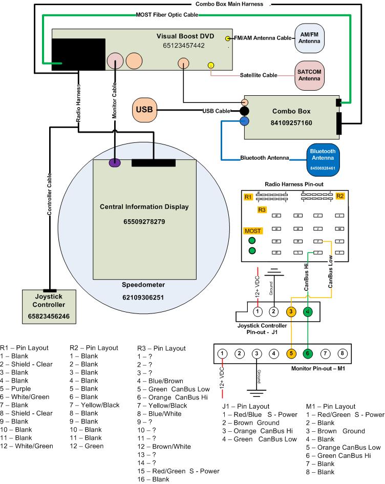
Can someone verify this for me? I have drawn up Smooth's Stuff, but I do not trust the Metra Diagram included in this thread. Additionally I would like the color codes matched up with what the wire does.
Example:
Red/Green - Switched Power
Red - Constant Power
Brown - Ground
Clear - Shielding
I've Attached a drawing of what I have so far. If we can get this completed, then many more can follow the diagrams to make their own set-up
The CAN BUS high and low in your pic is incorrect. I will look at my harness but it doesn't look right. The orange/green wire and the green wire are the can bus wires.
The blue wire to the Combox is not the Bluetooth antenna. the BT antenna is the small tan connector on the combox I still don't know what the blue connector on the combox does.
Hi there,
Does someone have the picture from Brad Bedell's first post ? I am seriously considering to get into the upgrade but want to secure it.
Many thanks in advance.
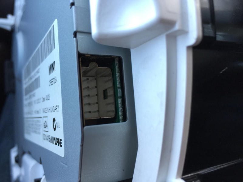
Anyone else run into the 10-pin cable with a 12-pin socket on the CID?
Ever heard the computer troubleshooting diagnosis of "problem exists between keyboard and chair"? It was one of those.
The CID screen has a side connector that is at the side of the rear panel, and a side connector that's really on the side. I failed to notice the real side side. Not one of my better moments.
Everything makes much more sense now. Here is a photo of the video connector in case anyone else ever tackles this and is confused as I was:
And here is a wider view for context:
The other back connector, 12 pin, is the one Brad described as being the power and CAN bus connector that only has a few pins connected.
I am not sure if you still read this tread but if you do I need your help with the monitor cable that is between the radio and the screen. My dealer here in Orlando can't find the cable and they are telling me that it is not available. If you have the part number can you post it here or PM me
I will work on a step by step guide with pictures but I am still waiting for parts to come in. Some of the parts are coming from Germany so it will take two to three weeks.
I am almost done my retrofit following this whole thread. Thanks a lot.
Now I am stuck with 3 things.
Both USB port not working, and I don't see the AUDIO option when pairing bluetooth iPhone, I can only use it as a phone within the car (receive and make calles).
I have a few questions if anyone can help, it will be appreciated.
1. The Black connector USB diagram?
2. The Blue connector USB diagram?
3. What are the optical cable used for?
I am almost done my retrofit following this whole thread. Thanks a lot.
Hey your post was a big help.
Now I am stuck with 3 things.
Both USB port not working, and I don't see the AUDIO option when pairing bluetooth iPhone, I can only use it as a phone within the car (receive and make calles).
I have a few questions anyone that can help, it will be appreciated.
1. The Black connector USB diagram?
2. The Blue connector USB diagram?
3. What are the optical cable used for?
So I am almost done with the retrofit I am still waiting for a FSC emulator from China but everything else is working. Here is a list of parts I purchased for the retrofit.
Donor Car: 2011-2014 Mini
Parts needed for the install
1 Connector Housing for Joystick - Part# 61138380696 (Joystick side)
1 Connector Housing for Joystick - Part# 61136954526 (Display side)
1 Display Cable for CIC - Part# 61119185171
1 Bluetooth Antenna – Part# 84506928461
1 Bluetooth Antenna Cable – (Order from this website https://www.pasternack.com)
1 Handbrake Console – Navigation - Part# 51162756157
1 Multifunction Box for Combox - Part# 65902752447 (Ordered from Germany it took 2 weeks to get it)
1 Multifunction Box cover - Part# 65902752523
1 USB Adapter Wiring Cable - Part# 61129255716 (USB cable for glovebox USB socket)
1 USB Socket – Part# 84109230248 (USB socket in glovebox for map updates)
2 Optical Fiber Cable 7m - Part# 61120142318 (Most Optical cable for Combox)
1 Connector Housing for fiber-optic cable - Part# 61136917978
2 Envelope F Optical Fiber Cab Connector - Part# 61138387214
6 Metal tube- Part# 61136918242 (Protection for fiber optic cable)
1 USB Extension Cable - Part# 61119129360 (USB cable for USB/AUX socket)
1 USB/AUX-IN Socket – Part# 84109229247
1 Socket Housing 26 POL - Part# 61136913626 (Combox connector)
1 Covering Cap 26 POL - Part# 61136913644 (Combox connector cover)
1 Speedometer with screen from http://www.car-part.com ($125.00 + shipping)
1 Navigation System CIC from http://www.car-part.com ($125.00 + shipping)
1 Joystick from http://www.car-part.com ($85.00 + shipping)
1 Combox from – Part# 84109248178 http://www.ebay.com ($150.00)
(This one was super difficult to get most junkyards have no idea what the hell is a combox and if they do than they want an arm and a leg for it. The one I got was from a 2013 BMW X1 it is the same as long as it is the Combox Media not the Telematics)
20 Pin 0.2-0.5mm for joystick cable and combox cable
22AWG wire for wiring (Find a wrecked BMW at a Junkyard and see if you can get the main harness you will have all the wires in the right colors and you may find some of the connectors also)
I purchased all the small parts at http://miniofmtlaurelpartsgiant.com
Other option is http://www.ecstuning.com (check prices at both places)
I used the wiring diagrams from this forum and so far everything is correct.
Combox Media 26 POL connector wiring:
1 Power T30
14 Ground
10 AUX GND
23 AUX NF L
24 AUX NF R
22 AUX BLNC
25 MIC+
12 MIC-
11 MIC BLNC
Most connector on the right side:
Fiber Optic cable from radio
Flashing the CIC to the correct VIN must be done with ICOM B because you need the fiber optic port to do it. Do not try this with K+DCAN cable because it will fail and your CIC will be dead until you find an ICOM to redo it. It will take a couple of hours to do all three modules. I used WinKFP to do it.
Helpful website for flashing the modules:
Read this post it will be a lot clearer what you have to do after. (You don’t have to use OPS, Icom will do the same thing.) http://www.bmwcoding.com/showthread....na-clone)-MOST
So I am almost done with the retrofit I am still waiting for a FSC emulator from China but everything else is working. Here is a list of parts I purchased for the retrofit.
 06-09-2014, 10:15 AM