How To Electrical ::Driving lights installation
#51
Does anyone know what the pushbutton in OEM driving light harness does?
I have OEM DLs and OEM harness, except I don't have OEM pushbutton and want to use my own switch from NAPA. The OEM connector to the pushbutton has 4 leads, labeled:
Pin 3 = LON (green wire), Pin 4 = LED (blue wire), Pin 1 = Klass 58g (grey/red wire that goes to Pin 48 on FRM X14261), and Pin 2 = Klass 31 (brown wire, to ground/chassis).
Does pushing the button (turning on lights) connect pins 1 and 3?
Thanks!
#53
Did some testing: Pin 3 is at Vcc (about 13.x V). Pin 2 is at Gnd. Pins 1 and 4 hard to tell. Bridging 1 to 3 will: while connected bring DLs to about 1/2 intensity ON, and when releasing bridge they will change state (so from OFF to ON, or from ON to OFF). So, this seems like some pulse signal that turns the DLs on or off in 2 steps probably to reduce power spikes. Now I'm trying to see how I can easily emulate that with a cheapo switch.
Pin 4 to LED to GND results in an LED being lit when DLs are on, dark when OFF.
Remaining unanswered question: should Pin 1 be held to GND when not MON (Momentary ON)?
Pin 4 to LED to GND results in an LED being lit when DLs are on, dark when OFF.
Remaining unanswered question: should Pin 1 be held to GND when not MON (Momentary ON)?
Last edited by Zephyr1; 11-15-2015 at 12:37 PM.
#55
[QUOTE=jackyiscxd;3256916]See that black box, that’s where the driving lights wires go. The box is held by 2 plastic nuts, remove them, disconnect all the wires from the box, then remove the socket casings of the X14260 and X14261, the casings held by those two taps.
Follow the guide to connect all the wires, remove the knee protection panel under the steering wheel, route the switch wire to the correct location. These two steps are the easiest parts. Attention: for 2010 and 2011 minis, you need connect wire A1 to pin 41(pin 41 has a yellow/red wire there, connect it with A1) . Don't connect A1 to pin4, the lights won't wok. Here I want to give special thanks to NM member "slimjimtell" without his help I wouldn't figure out the problem.
Installed Rally lights on 2013 R56 with Xeon headlights earlier this week. Same issue with pin 4 and connector A1 not providing power to the lights. Connected A1 to pin 41 (yellow/red wire) as mentioned above and the lights worked as they should.
Thanks the write up with pictures!
..
Last edited by fritz_stuff; 12-14-2017 at 03:52 PM.
#56
A little to add....
See that black box, that’s where the driving lights wires go. The box is held by 2 plastic nuts, remove them, disconnect all the wires from the box, then remove the socket casings of the X14260 and X14261, the casings held by those two taps.
Follow the guide to connect all the wires, remove the knee protection panel under the steering wheel, route the switch wire to the correct location. These two steps are the easiest parts. Attention: for 2010 and 2011 minis, you need connect wire A1 to pin 41(pin 41 has a yellow/red wire there, connect it with A1) . Don't connect A1 to pin4, the lights won't wok. Here I want to give special thanks to NM member "slimjimtell" without his help I wouldn't figure out the problem.


Follow the guide to connect all the wires, remove the knee protection panel under the steering wheel, route the switch wire to the correct location. These two steps are the easiest parts. Attention: for 2010 and 2011 minis, you need connect wire A1 to pin 41(pin 41 has a yellow/red wire there, connect it with A1) . Don't connect A1 to pin4, the lights won't wok. Here I want to give special thanks to NM member "slimjimtell" without his help I wouldn't figure out the problem.


The first picture in this post is the OP showing the clips on the X14260/X14261 socket casings that you unplug from the footwell module that you need to press open to slide the pin connector out so you can access the wires. Both of the socket casings are black. If you are using the factory install directions, it describes the the interior casing (the actual pin connector or pigtail) of X14260 as grey and X14261 as black. You can't actually tell that until you slide them out of the socket casings. This little tidbit had me stumped for a little while. I 'm attaching a diagram also that indicates which module is which in relation to the footwell module.
The second picture shows the socket (or pin connector) sliding out of the socket casing.
The third picture shows the wire spliced in. The only thing I would add here is that you should make sure that you splice high enough on the pigtail that you will be able to slide the socket casing back on. I mention this because there's not a lot of play in the pigtail, and you will be tempted to splice so low that you cannot get the connector back in the socket casing, prompting the invention of new words.
#57
First off - without a doubt, a VERY helpful post. I only want to add a few comments to help others who are fortunate enough to find this post when they are ready to install. Hopefully others will find these additional comments useful:
The first picture in this post is the OP showing the clips on the X14260/X14261 socket casings that you unplug from the footwell module that you need to press open to slide the pin connector out so you can access the wires. Both of the socket casings are black. If you are using the factory install directions, it describes the the interior casing (the actual pin connector or pigtail) of X14260 as grey and X14261 as black. You can't actually tell that until you slide them out of the socket casings. This little tidbit had me stumped for a little while. I 'm attaching a diagram also that indicates which module is which in relation to the footwell module.
The second picture shows the socket (or pin connector) sliding out of the socket casing.
The third picture shows the wire spliced in. The only thing I would add here is that you should make sure that you splice high enough on the pigtail that you will be able to slide the socket casing back on. I mention this because there's not a lot of play in the pigtail, and you will be tempted to splice so low that you cannot get the connector back in the socket casing, prompting the invention of new words.
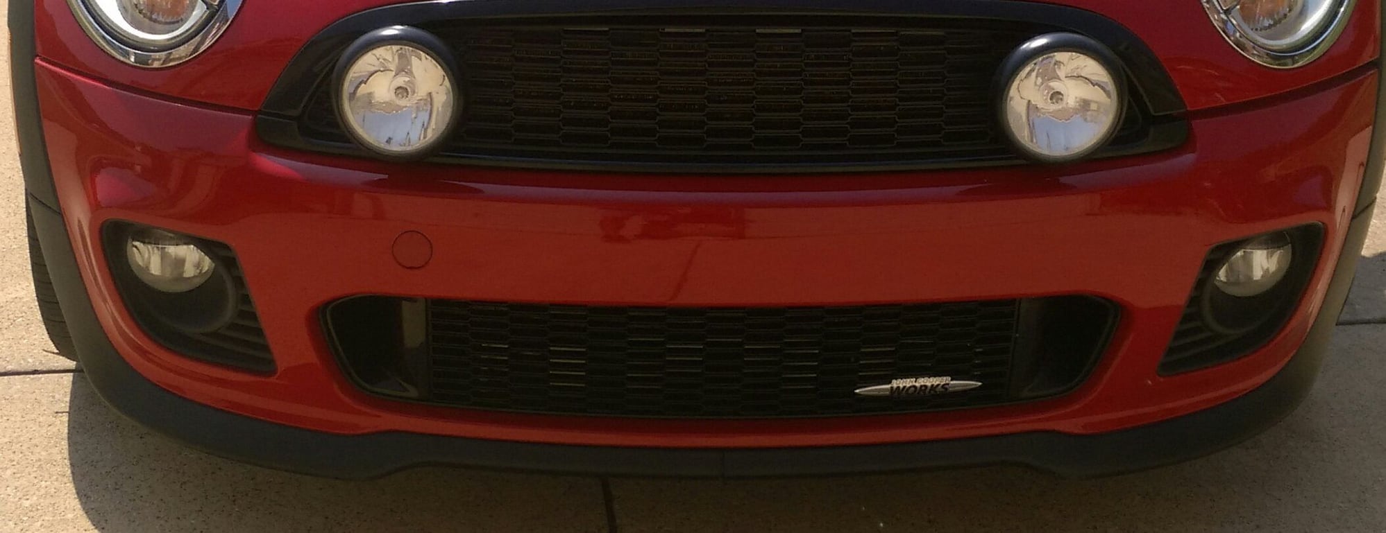
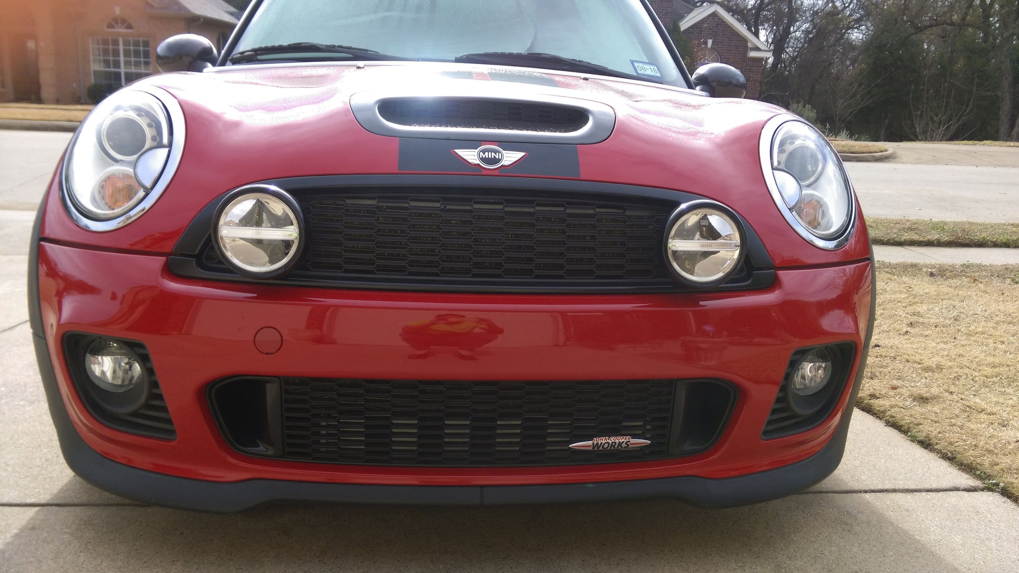
Also I recently upgraded from the Halogen to LED rally lights on my '11 JCW.
The are brighter and IMO look better. Cost was not great since I had to buy the entire kit to have black ones like my original ones.
The kit cam with a new control module which was a different part number than the new one with the LED's. (63 12 0 420 296 original), (63 12 2 289 191 new).
I tested the voltage output at the light socket with both modules installed and noticed a slight difference. The LED one was a few tenths (.1 - .3) of a volt less than the Halogen one. Not that this should make a difference I went with the new one just to be safe.
Here are some before and after pictures.


Last edited by fritz_stuff; 01-11-2018 at 08:23 AM.
#58
Help!
First of all, sorry about my English, I’m not a native English speaker but I will try my best to explain. If my words are not clear enough hopefully the pics will help. You can download the official installation guide from here:http://www.outmotoring.com/images/ho...aux_lights.PDF, I ordered my lights from outmotoring, their price is $100 lower than ebay and their customer service were very helpful, I chose the wrong color of the switch trim, they placed the special order for the color I want(carbon black) and gave me the exchange.
First step: disconnect the negative battery terminal.


First step: disconnect the negative battery terminal.


so I got a 2012 r56 S. Never wired anything into a car. Trying to follow these directions. Can anyone help me understand how to physically connect the wires? I have no clue how to actually connect the A1 with the M thing
Thread
Thread Starter
Forum
Replies
Last Post
igzekyativ
MINIs & Minis for Sale
34
07-16-2020 12:54 PM
squawSkiBum
MINI Parts for Sale
15
10-02-2015 09:21 AM


