Electrical 6 switch toggel panel pinouts and wiring diagram
#1
6 switch toggel panel pinouts and wiring diagram
Okay so after searching myself and seeing many others asking the same, i took apart and found out all the wiring etc. of the 6 switch toggle panel. i myself do not own a mini currently but found the switch panel sexy as hell and plan to fabricate it into my car soon. i wasn't sure where to post this but i feel this would be a big help to many out there and don't want it to be wasted on just myself.


-Switch 1 [left window]
a-pins 1 & 9
b-pins 2 & 9
-Switch 2 [DSC] (seems to be up and down position both do same thing)
a,b-pin 5 coming from left and pin 6 going right
-Switch 3 [power locks]
a-pins 9 & 16
b-pins 9 & 15
-Switch 4 [rear fogs] (same style as Switch 2)
a,b-pin 3 coming from left and pin 9 going right
-Switch 5 [front fogs] (same style as Switch 2)
a,b- pin 4 coming from left and pin 9 going right
-Switch 6 [right window]
a-pin 17 & 9
b-pin 18 & 9
To generalize some of the above info, switches (2,4,5), will turn the corresponding function on when the toggle switch is flipped in either direction.
**pins 10-14 are all linked together which are connected to the illuminating leds.
**pin 9 seems to be the ground since it is linked to all switches etc.
Pinout Wire Colors (main color, stripe color)
1-grey/black
2-grey/brown
3-black/yellow
4-yellow/black
5-blue/purple
6-green/blue
7-yellow/blue
8-yellow/brown(thicker)
9-brown/black
10-grey/red
11-grey/red
12-grey/red
13-blank
14-blank
15-yellow/red
16-yellow/brown
17-grey/blue
18-grey/yellow
****fyi-the actual pin #’s are different than the ones I labeled them as. After dissecting the pigtail further I found BMW’s pinout labeled on it. 1 is actually 10, 9 is actually 18, 10 is actually 1, and 18 is actually 9
Hopefully this helped a few of you out. Enjoy.
#3
just a quick question..im wondering about how these switches work for you guys...with say the fog switch...you flick the switch up or down ounce to power on and then again up or down to turn off?
if this is so it means you have an impulse relay or something to get this to work. anyone know where this is on the car or if it's not this way can you point me in the right direction.
#4
m wondering about how these switches work for you guys...with say the fog switch...you flick the switch up or down ounce to power on and then again up or down to turn off?
if this is so it means you have an impulse relay or something to get this to work. anyone know where this is on the car or if it's not this way can you point me in the right direction.
if this is so it means you have an impulse relay or something to get this to work. anyone know where this is on the car or if it's not this way can you point me in the right direction.
#6
The switches do not directly control anything. They are connected to the computer, which reads which switch was pressed (and in which direction), and the computer performs the appropriate function. The computer might simply flip a relay such as for a fog light, or perform the logic to send the window all the way down on a single click. The computer even turns on/off the LED indicator lights for the fogs (the switches don't do it). Think of it like a keyboard of a computer. All it does is send the keypress signals to the computer.
#7
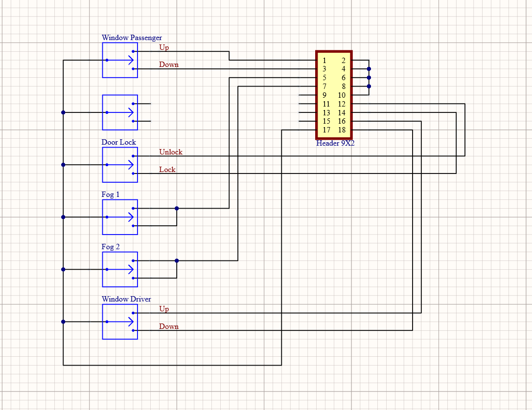
Mini Cooper Console Switch Schematic
Okay so after searching myself and seeing many others asking the same, i took apart and found out all the wiring etc. of the 6 switch toggle panel. i myself do not own a mini currently but found the switch panel sexy as hell and plan to fabricate it into my car soon. i wasn't sure where to post this but i feel this would be a big help to many out there and don't want it to be wasted on just myself.


-Switch 1 [left window]
a-pins 1 & 9
b-pins 2 & 9
-Switch 2 [DSC] (seems to be up and down position both do same thing)
a,b-pin 5 coming from left and pin 6 going right
-Switch 3 [power locks]
a-pins 9 & 16
b-pins 9 & 15
-Switch 4 [rear fogs] (same style as Switch 2)
a,b-pin 3 coming from left and pin 9 going right
-Switch 5 [front fogs] (same style as Switch 2)
a,b- pin 4 coming from left and pin 9 going right
-Switch 6 [right window]
a-pin 17 & 9
b-pin 18 & 9
To generalize some of the above info, switches (2,4,5), will turn the corresponding function on when the toggle switch is flipped in either direction.
**pins 10-14 are all linked together which are connected to the illuminating leds.
**pin 9 seems to be the ground since it is linked to all switches etc.
Pinout Wire Colors (main color, stripe color)
1-grey/black
2-grey/brown
3-black/yellow
4-yellow/black
5-blue/purple
6-green/blue
7-yellow/blue
8-yellow/brown(thicker)
9-brown/black
10-grey/red
11-grey/red
12-grey/red
13-blank
14-blank
15-yellow/red
16-yellow/brown
17-grey/blue
18-grey/yellow
****fyi-the actual pin #’s are different than the ones I labeled them as. After dissecting the pigtail further I found BMW’s pinout labeled on it. 1 is actually 10, 9 is actually 18, 10 is actually 1, and 18 is actually 9
Hopefully this helped a few of you out. Enjoy.


-Switch 1 [left window]
a-pins 1 & 9
b-pins 2 & 9
-Switch 2 [DSC] (seems to be up and down position both do same thing)
a,b-pin 5 coming from left and pin 6 going right
-Switch 3 [power locks]
a-pins 9 & 16
b-pins 9 & 15
-Switch 4 [rear fogs] (same style as Switch 2)
a,b-pin 3 coming from left and pin 9 going right
-Switch 5 [front fogs] (same style as Switch 2)
a,b- pin 4 coming from left and pin 9 going right
-Switch 6 [right window]
a-pin 17 & 9
b-pin 18 & 9
To generalize some of the above info, switches (2,4,5), will turn the corresponding function on when the toggle switch is flipped in either direction.
**pins 10-14 are all linked together which are connected to the illuminating leds.
**pin 9 seems to be the ground since it is linked to all switches etc.
Pinout Wire Colors (main color, stripe color)
1-grey/black
2-grey/brown
3-black/yellow
4-yellow/black
5-blue/purple
6-green/blue
7-yellow/blue
8-yellow/brown(thicker)
9-brown/black
10-grey/red
11-grey/red
12-grey/red
13-blank
14-blank
15-yellow/red
16-yellow/brown
17-grey/blue
18-grey/yellow
****fyi-the actual pin #’s are different than the ones I labeled them as. After dissecting the pigtail further I found BMW’s pinout labeled on it. 1 is actually 10, 9 is actually 18, 10 is actually 1, and 18 is actually 9
Hopefully this helped a few of you out. Enjoy.
There are backlight leds in the switch but I didnt
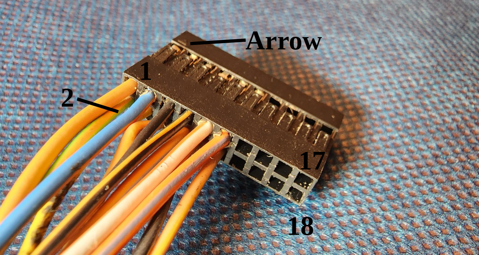
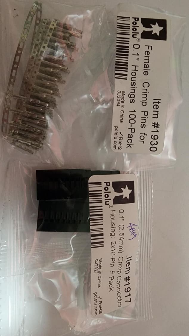
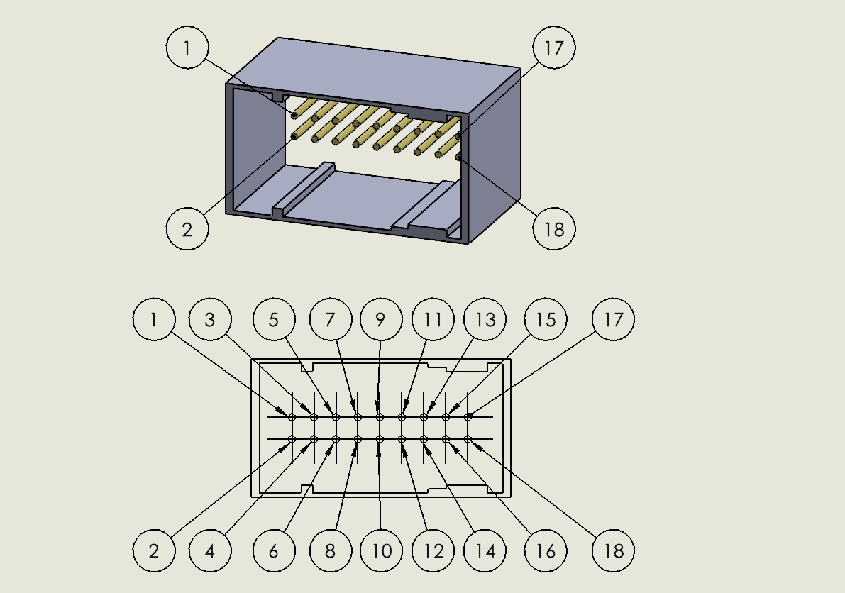
The connector is available from Core Electronics in Australia, its a wireable type and use standard IDC numbers as per diagrams. Pin 1 is defined with an arrow on the connector body and odd pin numbers (1,3,5 etc) on one side, evens on the other.


Thread
Thread Starter
Forum
Replies
Last Post
COOPT UP
R50/R53 :: Hatch Talk (2002-2006)
7
09-11-2015 04:59 AM
Navigation & Audio Portable Navigation XL Wiring
mikeandtricie
Navigation & Audio
3
09-04-2015 01:42 PM
doug5g
R50/R53 :: Hatch Talk (2002-2006)
0
09-02-2015 04:53 PM


