Drivetrain My build. Teaser photos and updates
#526
 08-06-2015, 07:12 AM


Can I just pay you to weld together a trellis subframe with mounts for a k20 conversion? Lol, whatever you'd charge would only be a fraction to what mini parts cost. I'm tired of seeing honda parts at a quarter of the price. Im ready to jump ship and make a bastard mini. Japanese and german love child. Along with my ducati my garage would be a mechanized axis powers. Great work though. You're inspiring to pull my welder out and get to practicing.
the vr6 would be cool, but they are heavy motors


#528
08-07-2015, 09:36 AM

4th Gear
#529
08-07-2015, 10:31 AM
#530
08-19-2015, 12:41 PM

So.. I have gotten bored.. ish.. lol! Decided to re-do a few things as I can now do them better than before. I also needed to make a few pieces to adapt between the -10 AN return line for the power steering and the hose that actually goes onto the pump.
And I want to look at being silly.. So I picked up 5 gallons of H2SO4 (sulfuric acid for the non chemically inclined), some household ammonia(in case sh** hits the proverbial fan. NH3 (a weak base) will combine with the sulfuric acid to neutralize it to an ammonium salt (ammonium sulfate) and water) ,
A 0-5A / 0-30V varriable DC power supply
Some dye's
And lots of prep materials, 6063 aluminum for making electrodes, and titanium wire for making jigs.
Whhaaaaa??!?!
anywho. First up. Adapter. -10AN compression to hose barb for PS return line.
start:

end!
Did not anodize this piece as it is buried and should not ever see any abrasion, chemical incompatibility, etc, and quite frankly because the anno stuff came on monday and I made this the friday before and wanted to just get it on the car and now it is buried so F it. ... phew
threads together nicely with a spare compression fitting I had laying around
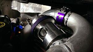
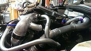
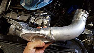
Now next up is re-making some of my intake plumbing.
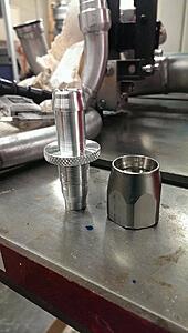
I needed a 2.5" vanjen joint and a 2" wiggins joint.
I also needed some way to hook the 2" to the 2.5" fitting somewhere in the middle with tubing.
Well.. the 2.5" tubing is really larger than I need with the way this setup is done, so the more of it I can make 2", the more space I have to put other things.
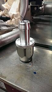
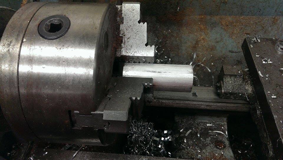
So I turned it out into the 2.5" ferrule.
Got to start somewhere:
And end somewhere else :cheers:
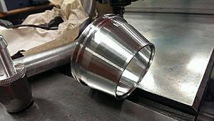
mmm purdy
(not pictured: the 2" wiggins ferrule.. apparently I forgot to snap a pick of it.. whoops)
So why do this?
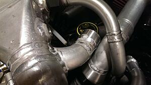
Well.. I decided to re-rout my boost mid-pipe so that I can actually fit this little thing called a water resevoir in my engine bay... in a spot that is not right over a hot exhaust would be nice.
think it will work (new tubing welded and run )
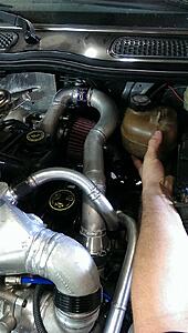
Now I just have to design up a new SC BPV (Same Idea but adding a few more features now that my lathe skills have gone up)
but now.. ITS CHEMISTRY TIME!!! MWAHAHHAAHAHAH!!!
hahahahaahaha

hahahaha!!!
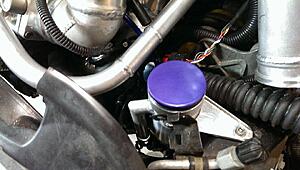
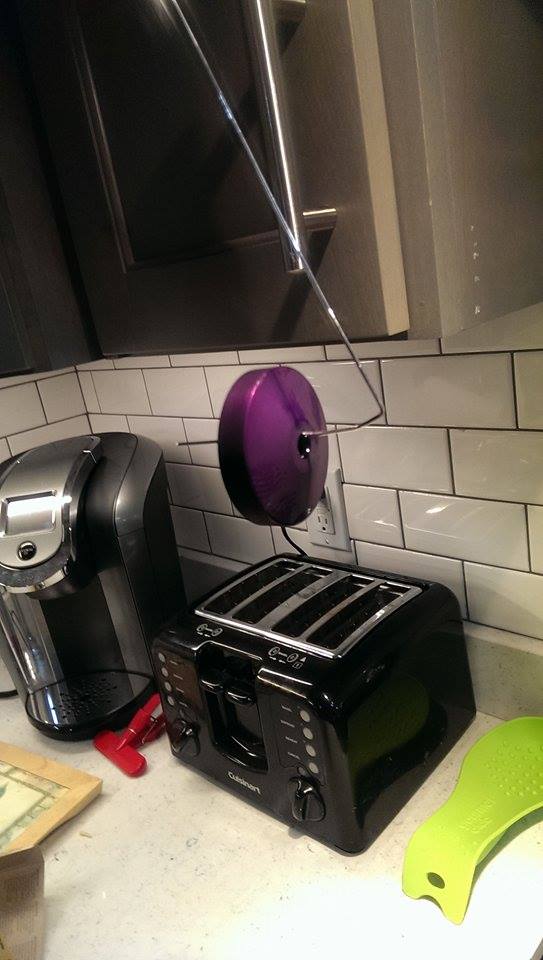
(actually I will be re-doing part of this one. The light spots are from trace oils that were on it and prevented anodizing and I got the color too blue to match the wigging fitting)
in all fairness it looked right in the light upstairs ...
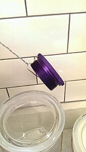
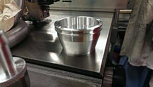
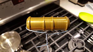
(Power steering reservoir cap btw... also turned it by hand!)
And I want to look at being silly.. So I picked up 5 gallons of H2SO4 (sulfuric acid for the non chemically inclined), some household ammonia(in case sh** hits the proverbial fan. NH3 (a weak base) will combine with the sulfuric acid to neutralize it to an ammonium salt (ammonium sulfate) and water) ,
A 0-5A / 0-30V varriable DC power supply
Some dye's
And lots of prep materials, 6063 aluminum for making electrodes, and titanium wire for making jigs.
Whhaaaaa??!?!
anywho. First up. Adapter. -10AN compression to hose barb for PS return line.
start:
end!

Did not anodize this piece as it is buried and should not ever see any abrasion, chemical incompatibility, etc, and quite frankly because the anno stuff came on monday and I made this the friday before and wanted to just get it on the car and now it is buried so F it. ... phew
threads together nicely with a spare compression fitting I had laying around


Now next up is re-making some of my intake plumbing.
I needed a 2.5" vanjen joint and a 2" wiggins joint.
I also needed some way to hook the 2" to the 2.5" fitting somewhere in the middle with tubing.
Well.. the 2.5" tubing is really larger than I need with the way this setup is done, so the more of it I can make 2", the more space I have to put other things.
So I turned it out into the 2.5" ferrule.
Got to start somewhere:

And end somewhere else :cheers:

mmm purdy

(not pictured: the 2" wiggins ferrule.. apparently I forgot to snap a pick of it.. whoops)
So why do this?
Well.. I decided to re-rout my boost mid-pipe so that I can actually fit this little thing called a water resevoir in my engine bay... in a spot that is not right over a hot exhaust would be nice.
think it will work (new tubing welded and run )

Now I just have to design up a new SC BPV (Same Idea but adding a few more features now that my lathe skills have gone up)
but now.. ITS CHEMISTRY TIME!!! MWAHAHHAAHAHAH!!!

hahahahaahaha
hahahaha!!!

(actually I will be re-doing part of this one. The light spots are from trace oils that were on it and prevented anodizing and I got the color too blue to match the wigging fitting)
in all fairness it looked right in the light upstairs ...

(Power steering reservoir cap btw... also turned it by hand!)
#532
08-26-2015, 06:19 AM

#533
08-26-2015, 01:48 PM
#534
10-07-2015, 07:21 AM
so I also did a thing...
made a new bypass valve! With some extra features:
the thing!
With no inlet
Decided to go with my engineering gut and determined that this would be okay and would not bite me... so I moved the pick-up point to post intercooler hope I'm right!
  (will not be any reversion of flow while in boost... theory says I am correct... Old method made it too much of a pain to get to spark plugs...
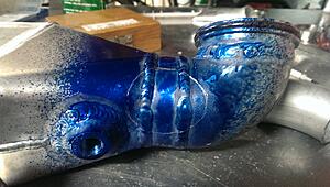
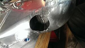
So I cut off the old piece and welded a plate over it.
Marked a new hole
cut a new hole
welded up a new outlet
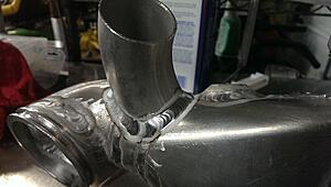
made an angle adjustment.
and machined and welded on a seat
Then on to finishing the valve!
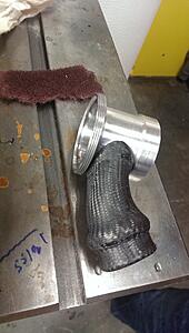
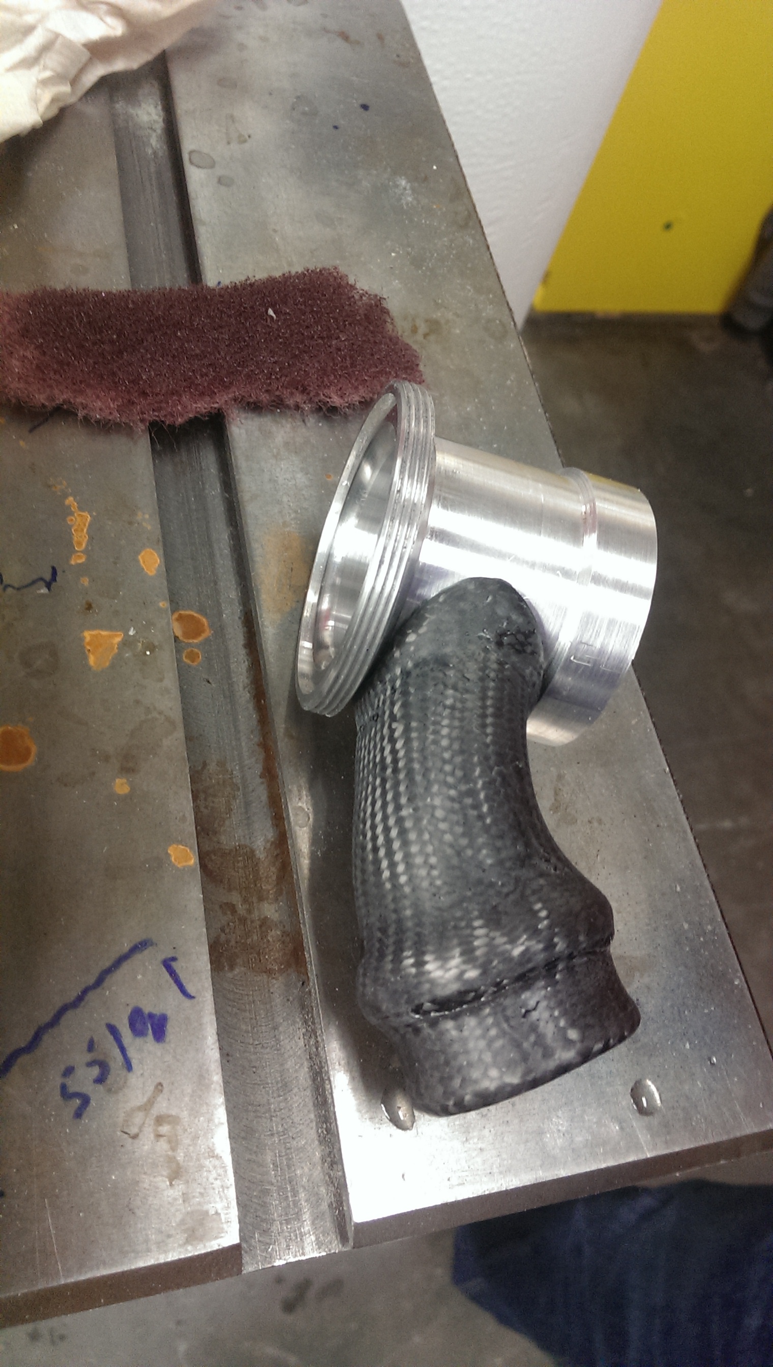
solid carbon inlet tube in progress - it's bent to parallel the inlet tube.
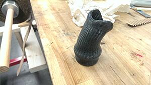
What a PITA, but it is strong as hell!
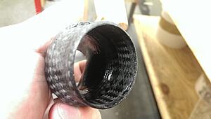
test fit
Blurry shot... Apologies. But the tube is bonded and not coming off!
Used ScotchWeld DP420 . Good industrial grade stuff meant for this type of work. The bond should be stronger than the base material. Just hope it holds up well to heat cycling etc! (should be good for it.. but who knows.. :| )
Have the T-bolt clamps and silicon tubing the right size coming in later this week. Stay posted!
made a new bypass valve! With some extra features:
- Measures 1" shorter than previous version
- more simple machining geometry
- better fitment of interlocking parts
- threaded ring to close (less bulkey than v-band clamp
- snap-ring to attach base to plumbing (vs welded) - allows for the re-use of the valve with only re-machining of the ferrule / valve seat
- carbon fiber molded inlet.. because why not? (fiberglass just on the interface to prevent galvanic corrosion)
the thing!
With no inlet

Decided to go with my engineering gut and determined that this would be okay and would not bite me... so I moved the pick-up point to post intercooler
hope I'm right! (will not be any reversion of flow while in boost... theory says I am correct... Old method made it too much of a pain to get to spark plugs... So I cut off the old piece and welded a plate over it.
Marked a new hole

cut a new hole

welded up a new outlet
made an angle adjustment.

and machined and welded on a seat

Then on to finishing the valve!
solid carbon inlet tube in progress - it's bent to parallel the inlet tube.

What a PITA, but it is strong as hell!

test fit
Blurry shot... Apologies. But the tube is bonded and not coming off!
Used ScotchWeld DP420 . Good industrial grade stuff meant for this type of work. The bond should be stronger than the base material. Just hope it holds up well to heat cycling etc! (should be good for it.. but who knows.. :| )
Have the T-bolt clamps and silicon tubing the right size coming in later this week. Stay posted!

#535
10-07-2015, 11:29 PM


#538
02-05-2016, 08:43 PM
okay, long overdue, and only partial update.
So the new car has been a lot of fun, and I have been working on it some, lots of other side projects, and been getting into horseback riding with the girlfriend. (trail riding)
but anywho.
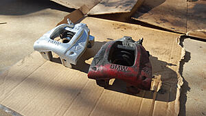
Took all of the calipers off, replaced dust boots, guide pins, sleeves etc etc, then also wire brushed all the old paint off and gave them a fresh spray of silver caliper paint:
In other boosty boost news...
I decided to.. at least table the air-to-water intercooler setup. The car was just a little too loud with just the one straight through muffler, and space was becoming a challenge with all of the water lines.
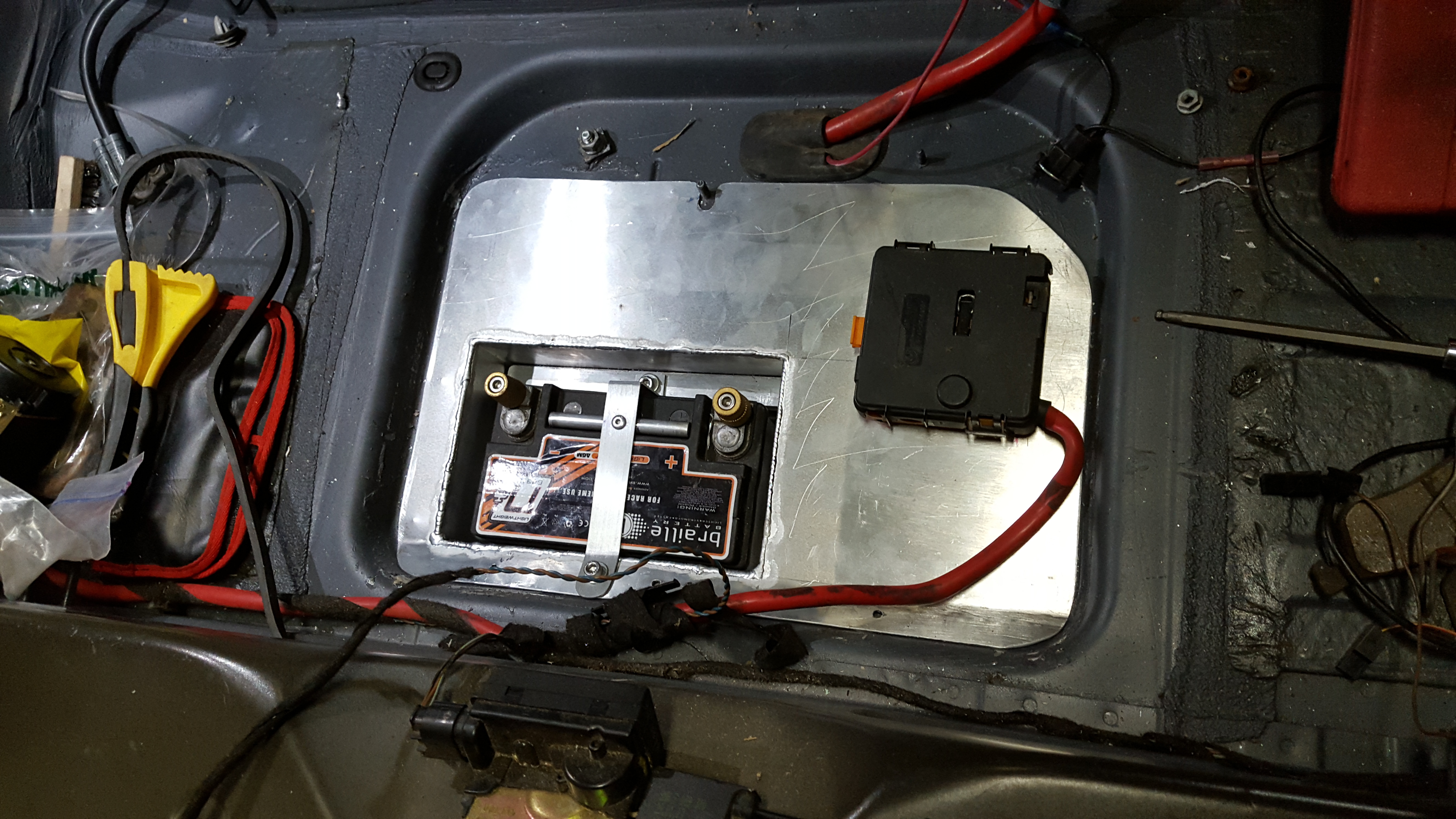
So ditching all of that means I can make the battery box smaller, which means more room for exhaust work.. I could add in a bypass.. eh. save that idea for later.
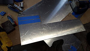
but first, re-made the battery box during a snow day!
Sheet was too large for the bandsaw, so I chucked up a metal blade in the jig saw, broke out the cutting fluid, square, tape (to keep from hurting the finish), markers, and measurement tools and got to laying out!
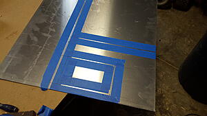
cutting
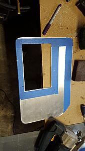
check-fit
making the battery box part of it
and when you don't have access to a box and pan brake, you make your own.
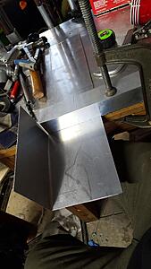
voila!!! (sp?)
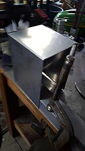
weld weld weld weld weld
(and cut some relief holes for that fuse box thingy)
detal shot... meh..
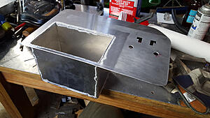
riveted in a piece of channel part way down the box and bend this little thingy up.
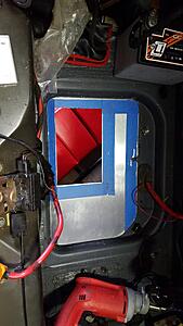
and the final test fit!

only thing left to do was to transfer drill some holes from the sheet metal and throw in some rivets.
(now the only thing left to do at some point is drill out the rivets, put down some body sealant... or silicone... and then put it all back down.)
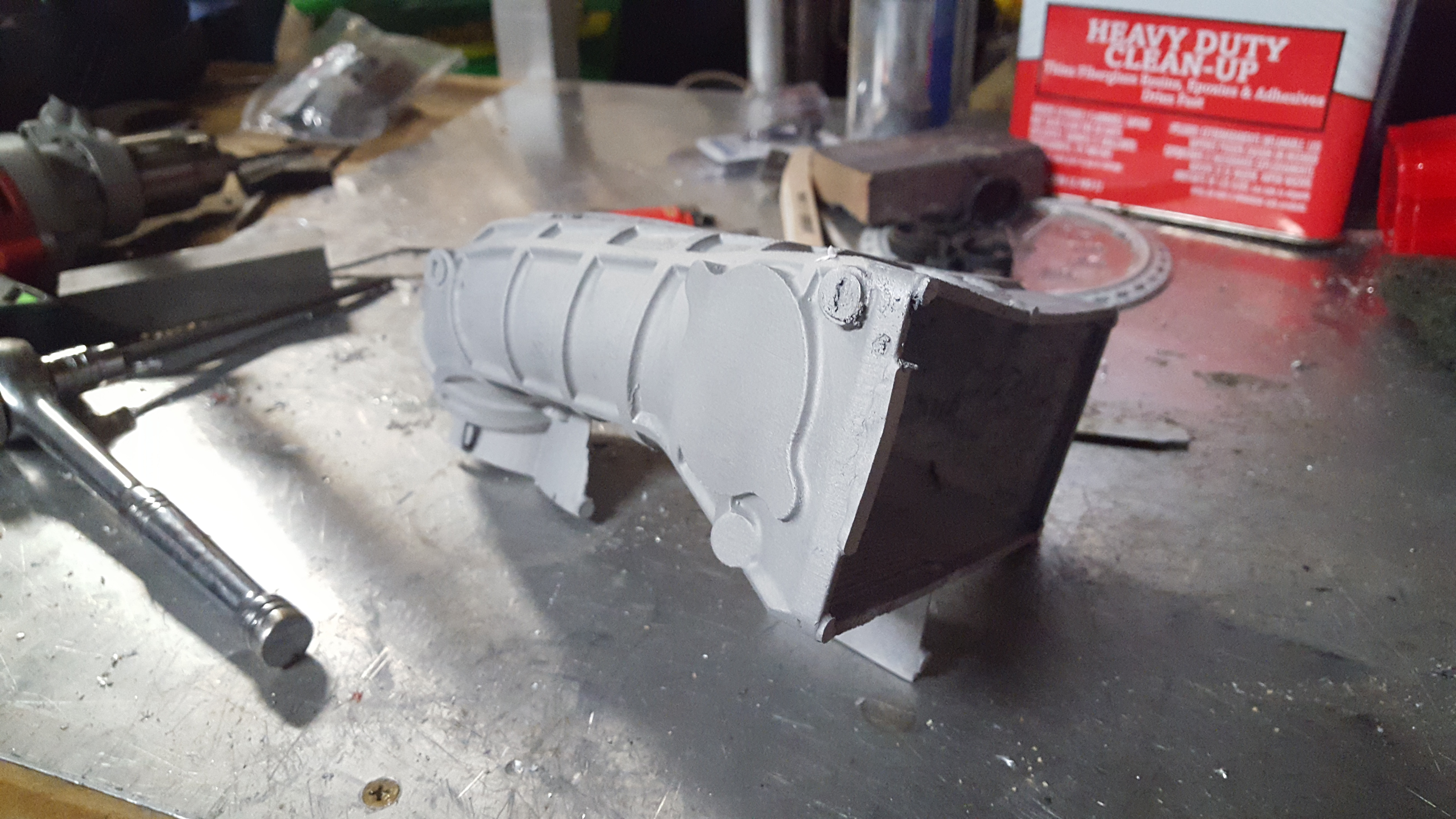
Next up!! A little treat of something to come.
Past prototype 1, and prototype 2 is on the way...
Yes.. this is cast aluminum... tried to be crafty and investment some ABS, but the burnout didn't go as well as hoped, so some residual plastic was in the cavity and caused some unwanted porosity.
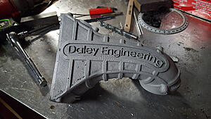
also had some minor (was correctable via some heat and a hammer) warping
Current revision I made a prototype out of delrin, and am casting it in silicone to make a negative (silicone got here today!) From that I can make wax positives (yes I used the plural... may take a few attempts, but hopes for the first one!) and do investment casting with a proper wax master.
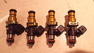
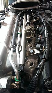
Anywho, next up was for piece of mind. Injector extensions.
I ordered (a long time ago when I got my injectors) some extensions... 14mm I think? something. One of the standards. Next side was 25mm... and by all accounts the 14mm should have worked, but after some measuring what I decided would be best was 20mm.
But! They didn't have grooves on them to hook the factory injector clips to locate them... so if you fully seated the extensions in the fuel rail and then went to bolt it on the car... lets just say the o-rings just contacted the outer surface of the ports on the intake manifold...
So I just sort of pushed the clips on anyways... and it held them in place... ish.. but not a good solution...
So I decided to turn out some new ones!!
(old left, mine right)
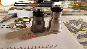
After I did a few test fits, I made a few minor changes (a few .001's" here and there)
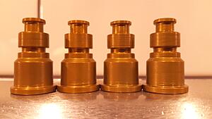
and made a set of 4!
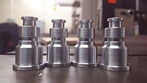
had to grind some tool steel to make a boring bar to do the inside walls and back face and get a good enough surface finish for an o-ring seat.
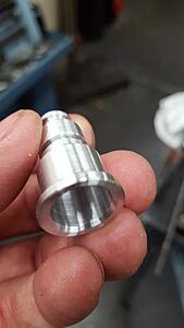
then they went into my home-brew ano tank.
(along with a hose connector I needed.. will be the color test)
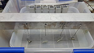
color test!!
sealing the parts:
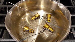
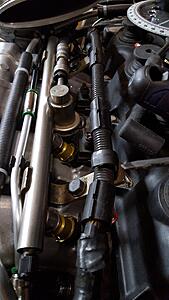
mounted on the injectors
and mounted on the fuel rails in the car! woot!
And that is all folks!

So the new car has been a lot of fun, and I have been working on it some, lots of other side projects, and been getting into horseback riding with the girlfriend. (trail riding)
but anywho.
Took all of the calipers off, replaced dust boots, guide pins, sleeves etc etc, then also wire brushed all the old paint off and gave them a fresh spray of silver caliper paint:

In other boosty boost news...
I decided to.. at least table the air-to-water intercooler setup. The car was just a little too loud with just the one straight through muffler, and space was becoming a challenge with all of the water lines.
So ditching all of that means I can make the battery box smaller, which means more room for exhaust work.. I could add in a bypass.. eh. save that idea for later.
but first, re-made the battery box during a snow day!
Sheet was too large for the bandsaw, so I chucked up a metal blade in the jig saw, broke out the cutting fluid, square, tape (to keep from hurting the finish), markers, and measurement tools and got to laying out!

cutting

check-fit

making the battery box part of it

and when you don't have access to a box and pan brake, you make your own.

voila!!! (sp?)

weld weld weld weld weld
(and cut some relief holes for that fuse box thingy)

detal shot... meh..

riveted in a piece of channel part way down the box and bend this little thingy up.

and the final test fit!
only thing left to do was to transfer drill some holes from the sheet metal and throw in some rivets.

(now the only thing left to do at some point is drill out the rivets, put down some body sealant... or silicone... and then put it all back down.)
Next up!! A little treat of something to come.
Past prototype 1, and prototype 2 is on the way...
Yes.. this is cast aluminum... tried to be crafty and investment some ABS, but the burnout didn't go as well as hoped, so some residual plastic was in the cavity and caused some unwanted porosity.

also had some minor (was correctable via some heat and a hammer) warping
Current revision I made a prototype out of delrin, and am casting it in silicone to make a negative (silicone got here today!) From that I can make wax positives (yes I used the plural... may take a few attempts, but hopes for the first one!) and do investment casting with a proper wax master.
Anywho, next up was for piece of mind. Injector extensions.
I ordered (a long time ago when I got my injectors) some extensions... 14mm I think? something. One of the standards. Next side was 25mm... and by all accounts the 14mm should have worked, but after some measuring what I decided would be best was 20mm.
But! They didn't have grooves on them to hook the factory injector clips to locate them... so if you fully seated the extensions in the fuel rail and then went to bolt it on the car... lets just say the o-rings just contacted the outer surface of the ports on the intake manifold...
So I just sort of pushed the clips on anyways... and it held them in place... ish.. but not a good solution...
So I decided to turn out some new ones!!
(old left, mine right)

After I did a few test fits, I made a few minor changes (a few .001's" here and there)
and made a set of 4!

had to grind some tool steel to make a boring bar to do the inside walls and back face and get a good enough surface finish for an o-ring seat.

then they went into my home-brew ano tank.
(along with a hose connector I needed.. will be the color test)

color test!!

sealing the parts:


mounted on the injectors

and mounted on the fuel rails in the car! woot!

And that is all folks!
Last edited by soccerbummer1104; 02-05-2016 at 08:48 PM.
#540
02-05-2016, 10:09 PM
Speaking of... I forgot a few...
When you can't seem to find a band-clamp the right size, you cut some out and weld it back :3
Then I (somewhat sadly) had to modify THE VERY FIRST! thing I actually made for this project... (I think...)
The SC inlet tube...
Long story short, among some clearance issues, and the swap to a thicker radiator... I had to clearance the tube for the fan motor.
Eh... it worked.
clearance achieved!
Then I decided to make my vacuum lines a combination of push connect, aluminum tubing, and flex hose.
For the tube ends I made a little mandrel (I can share pics if would like) and sort of made my own bubble flare to keep the tubing from backing off.
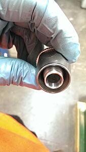
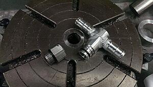
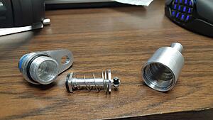
next up!, a swivel water fitting with a straight thread that fits in an NPT port (tapered thread, seals with o-ring)
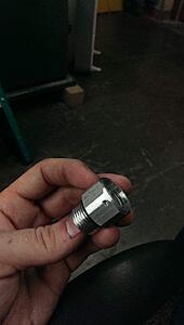
bottom groove has the swivel sealing o-ring, the top groove has a corresponding inner groove in the threaded piece that the hole in the last image leads into.
When you put these two parts together the o-ring seals, but a piece of aluminum welding wire if fed in through the port and when given proper motivation (pushed with a pair of pliers in small increments while twisting the fitting in the right direction) the wire (.063" dia to each groove depth of .033") holds the two pieces together.
(you would have to shear the wire all the way around for it to come off. this is much the same way that some high-end air cylinders are put together, and a similar way that a lot of high-dollar AN swivel fittings are constructed)

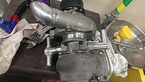
Made two of them, the 90� adapter is the water inlet to the turbo cooling jacket, and is fed from the heater core outlet.
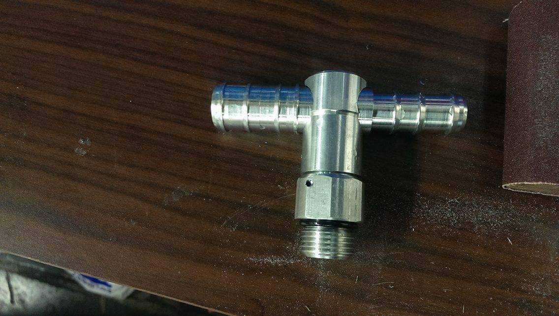
The T fitting has a larger and smaller port.
The larger port is sized for the water reservoir, (fill line) and the smaller port is the same size as the water pump small inlet.... and that is where it goes.
no water should go to the reservoir from this point as the reservoir is also fed via a small breather line just after the thermostat (slightly higher pressure) which will, if anything, cause a small amount of flow to go from the large port towards the smaller port (but not much)
When you can't seem to find a band-clamp the right size, you cut some out and weld it back :3

Then I (somewhat sadly) had to modify THE VERY FIRST! thing I actually made for this project... (I think...)
The SC inlet tube...
Long story short, among some clearance issues, and the swap to a thicker radiator... I had to clearance the tube for the fan motor.
Eh... it worked.

clearance achieved!

Then I decided to make my vacuum lines a combination of push connect, aluminum tubing, and flex hose.
For the tube ends I made a little mandrel (I can share pics if would like) and sort of made my own bubble flare to keep the tubing from backing off.

next up!, a swivel water fitting with a straight thread that fits in an NPT port (tapered thread, seals with o-ring)

bottom groove has the swivel sealing o-ring, the top groove has a corresponding inner groove in the threaded piece that the hole in the last image leads into.
When you put these two parts together the o-ring seals, but a piece of aluminum welding wire if fed in through the port and when given proper motivation (pushed with a pair of pliers in small increments while twisting the fitting in the right direction) the wire (.063" dia to each groove depth of .033") holds the two pieces together.
(you would have to shear the wire all the way around for it to come off. this is much the same way that some high-end air cylinders are put together, and a similar way that a lot of high-dollar AN swivel fittings are constructed)

Made two of them, the 90� adapter is the water inlet to the turbo cooling jacket, and is fed from the heater core outlet.
The T fitting has a larger and smaller port.
The larger port is sized for the water reservoir, (fill line) and the smaller port is the same size as the water pump small inlet.... and that is where it goes.
no water should go to the reservoir from this point as the reservoir is also fed via a small breather line just after the thermostat (slightly higher pressure) which will, if anything, cause a small amount of flow to go from the large port towards the smaller port (but not much)

#542
02-08-2016, 06:19 AM

Platinum Sponsor
Great thread, looks like some progress, that work on the pipe. Very nice.
__________________

MINI Guru/ MINI Owner Since 2004 | NEW Lifetime Part Replacement | Local Pickup
Milltek | Genuine MINI | Forge Motorsport | NM Engineering | ECS Performance | M7 Speed
Customer Service Hours: 8am-8pm EST|Sales Team Hours: 8am-11pm | SAT 10am-7pm 800.924.5172
MINI Guru/ MINI Owner Since 2004 | NEW Lifetime Part Replacement | Local Pickup
Milltek | Genuine MINI | Forge Motorsport | NM Engineering | ECS Performance | M7 Speed
Customer Service Hours: 8am-8pm EST|Sales Team Hours: 8am-11pm | SAT 10am-7pm 800.924.5172

#544
04-14-2016, 07:07 AM
well, Car is running and idling again.. (just got it together to check for coolant leaks and check the power steering setup and oil cooler setup )
I don't have the oil temp and pressure sensors set up yet, but after 20 minutes of idling (not a huge surprise) the oil never got hot enough to open the thermostat valve and send it to the heat exchanger.
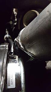
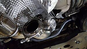
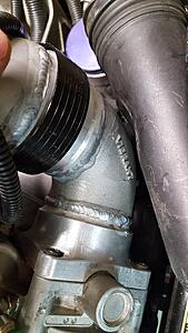
Anywho.. the old Downpipe hit the swaybar whenever the suspension loaded, so I decided to cut it apart and start welding a new downpipe and wastegate dump together.
Making sure to take some lessons learned over the past two years. (two flex pieces in the waste gate dump, at each end, Clamps to make it a separate piece that I can install up in the engine first, and then the downtube, and then hook them together.. etc etc. Just makes installing less of a PITA... )
anywho... some welds first, then some install shots.
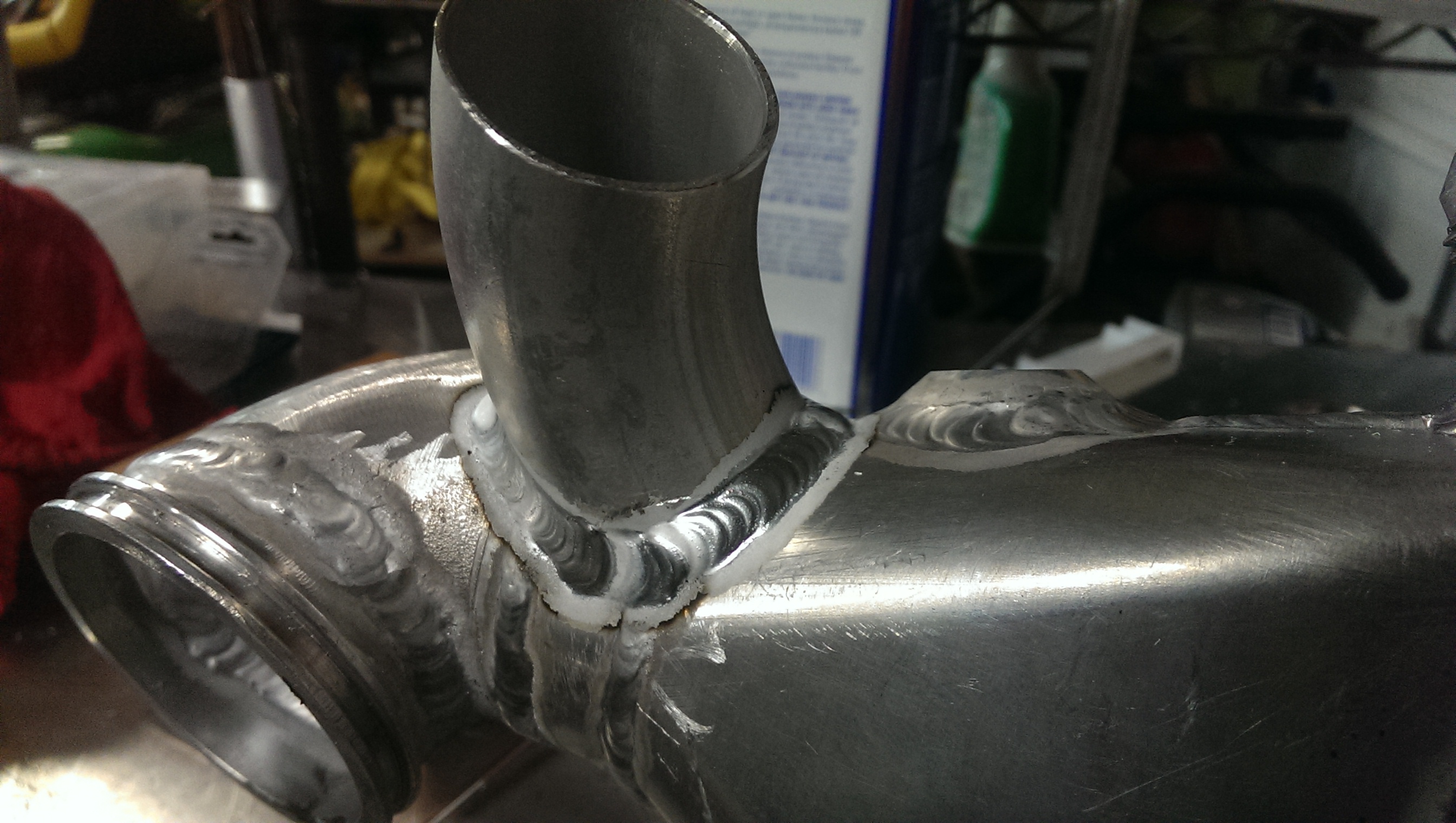
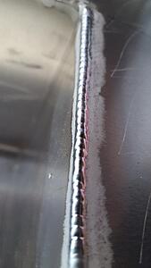
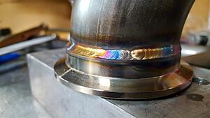
Proud of this, but I was just getting back into the swing of things (have not done stainless in quite some time)
Room for improvement.
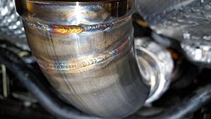
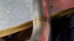
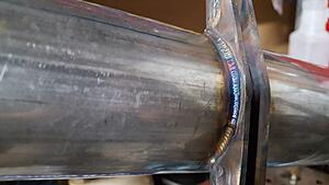
After several more welds, an good autogenous opportunity showed itself, so I took it.
60hz pulse, no filler, 72A foreground, 45amp background, 75% foreground duty. full penetration and argon purged. Using a large (1" diameter) pyrex cup.
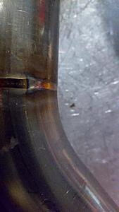
The fillet weld is a bit undercut.. sure... but it was a used flex coupling that I cut off of the old downtube so there was a .120 wall on the end of the coupler that I welded through and pulled down into the .063 tube.. I don't expect any issues.
And if there is I can simply clean it and re-weld at some point down the road.
Showing that the butt joint was not undercut.
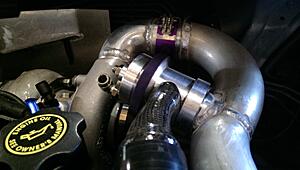
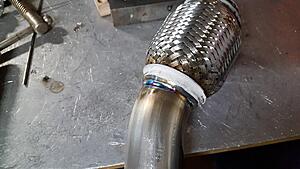
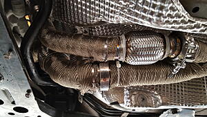
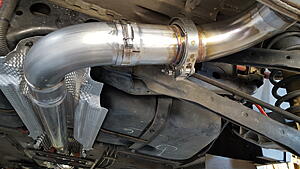
and some install photos
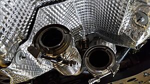
you can see the other flex coupling on the downpipe in that photo (non braided)
slightly different angle
Lots of other stuff in progress as well..
Working on the third revision of the diverter valve. The mahcined one with the carbon snout worked well, but I have concerns as to the longevity of the carbon piece. (epoxy concerns) - I'm sure the layup is not devoid of pores, so thermal cycling and those trapped gasses causing issues, on top of the lifetime degradation of the epoxy while seeing higher service temperatures.
Yes there are composites that can see the service temperatures of an engine bay, and I even have some, but I was thinking back and think I done goofed and used the wrong one when I made this layup (SMH...)
Anywho, I wanted to try a different design, and as much as I love the diaphram setup, I am trying an o-ring sealed version again, with a whole lot of machined goodies to it.
(interchangeable port styles, etc)
preview:
I don't have the oil temp and pressure sensors set up yet, but after 20 minutes of idling (not a huge surprise) the oil never got hot enough to open the thermostat valve and send it to the heat exchanger.
Anywho.. the old Downpipe hit the swaybar whenever the suspension loaded, so I decided to cut it apart and start welding a new downpipe and wastegate dump together.
Making sure to take some lessons learned over the past two years. (two flex pieces in the waste gate dump, at each end, Clamps to make it a separate piece that I can install up in the engine first, and then the downtube, and then hook them together.. etc etc. Just makes installing less of a PITA... )
anywho... some welds first, then some install shots.
Proud of this, but I was just getting back into the swing of things (have not done stainless in quite some time)
Room for improvement.

After several more welds, an good autogenous opportunity showed itself, so I took it.
60hz pulse, no filler, 72A foreground, 45amp background, 75% foreground duty. full penetration and argon purged. Using a large (1" diameter) pyrex cup.


The fillet weld is a bit undercut.. sure... but it was a used flex coupling that I cut off of the old downtube so there was a .120 wall on the end of the coupler that I welded through and pulled down into the .063 tube.. I don't expect any issues.
And if there is I can simply clean it and re-weld at some point down the road.
Showing that the butt joint was not undercut.

and some install photos

you can see the other flex coupling on the downpipe in that photo (non braided)
slightly different angle

Lots of other stuff in progress as well..
Working on the third revision of the diverter valve. The mahcined one with the carbon snout worked well, but I have concerns as to the longevity of the carbon piece. (epoxy concerns) - I'm sure the layup is not devoid of pores, so thermal cycling and those trapped gasses causing issues, on top of the lifetime degradation of the epoxy while seeing higher service temperatures.
Yes there are composites that can see the service temperatures of an engine bay, and I even have some, but I was thinking back and think I done goofed and used the wrong one when I made this layup (SMH...)
Anywho, I wanted to try a different design, and as much as I love the diaphram setup, I am trying an o-ring sealed version again, with a whole lot of machined goodies to it.
(interchangeable port styles, etc)
preview:

#546
05-17-2016, 01:49 PM
so a thing happened....
Other things can be seen teasing in the background.
(I am excited!)
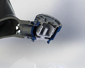
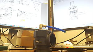
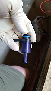
This is one of those things.
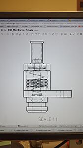
As it turns out, the original PCV valve is just a spring and a flat plate on the inside. Since the PCV now has a source that is after the throttle, and the throttle is pressurized, it needed to seal under pressure. This is essentially a factory replacement that *should* (we will see after I make the first prototype) work, and throttle vacuum as the original valve did, but also seals under positive pressure.
Lots of other boring stuff.
May post more of it later.
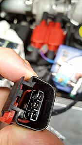
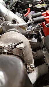
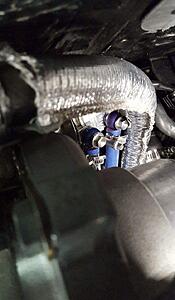
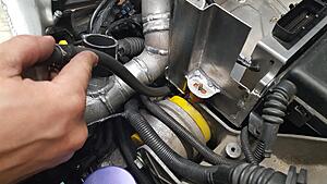
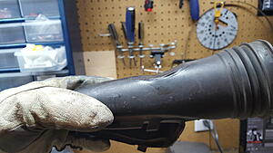
But the boring one I choose for now is what to do if your ignition cable sheath it looking worse for wear.. as mine was.. as well as I needed to better heat shield it from the turbo.
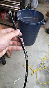
The original cable.
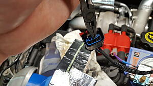
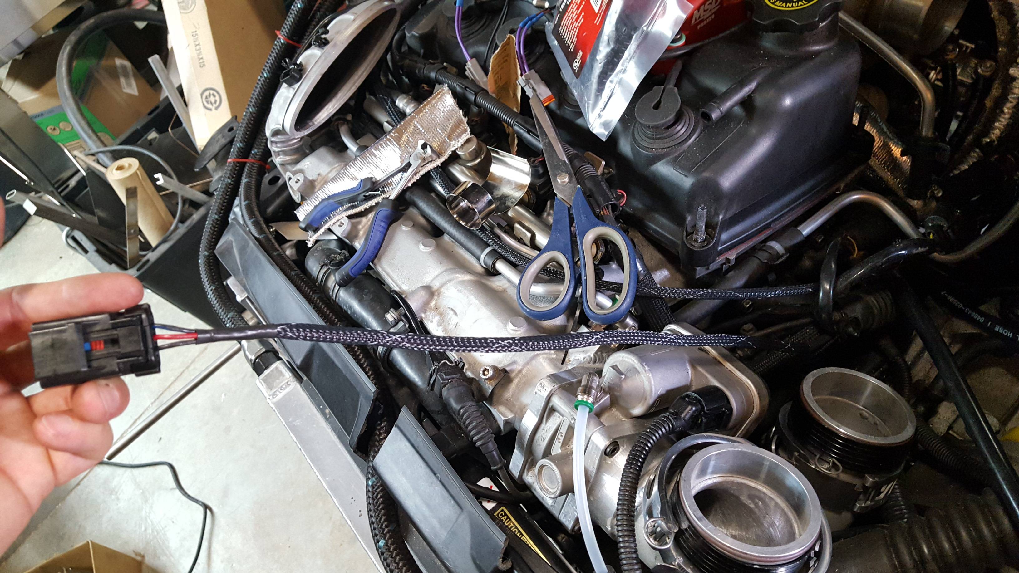
A little out of order, but I went back and took some photos.
start by using a pair of needle nose pliers to remove the blue secondary connector from the housing. Just grip firmly and pull. It should come out completely.
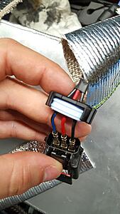
Next pry out slightly on each side on the back to remove the clip that holds in the silicone gasket around the wires.
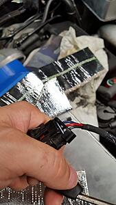
After you remove both sides of that, then one at a time apply tension to a cable and then click up the little black tab over the connector on the wire that you are applying tension too. The pin socket should slide back easily. Once you release all sockets, pull on the wires (genltly) and the silicone gasket and wires should come out of the back of the housing. Note the colors of the wires and their position in the housing (don't want to mix those up!)
After that I removed the silicone gasket (simply pull the wires through it), the plastic backing, and then slide off the old cover.
I used a woven nylon abrasive resistant and flame retardant sleeve (from mcmaster) and some heat shrink tubing.
(I later took it back apart)
because I needed to add some heat protection.
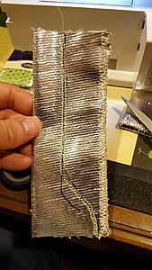
but I didn't need it as bulky as the cover I had, so out came the sewing machine.. and didn't want to upset.. anyone... so I left the color that was in it alone. .
.
traced a profile, selected a pattern, an ran a crude line.
reassemble everything else. and good to go!
Other things can be seen teasing in the background.

(I am excited!)
This is one of those things.

As it turns out, the original PCV valve is just a spring and a flat plate on the inside. Since the PCV now has a source that is after the throttle, and the throttle is pressurized, it needed to seal under pressure. This is essentially a factory replacement that *should* (we will see after I make the first prototype) work, and throttle vacuum as the original valve did, but also seals under positive pressure.
Lots of other boring stuff.
May post more of it later.
But the boring one I choose for now is what to do if your ignition cable sheath it looking worse for wear.. as mine was.. as well as I needed to better heat shield it from the turbo.

The original cable.
A little out of order, but I went back and took some photos.
start by using a pair of needle nose pliers to remove the blue secondary connector from the housing. Just grip firmly and pull. It should come out completely.

Next pry out slightly on each side on the back to remove the clip that holds in the silicone gasket around the wires.

After you remove both sides of that, then one at a time apply tension to a cable and then click up the little black tab over the connector on the wire that you are applying tension too. The pin socket should slide back easily. Once you release all sockets, pull on the wires (genltly) and the silicone gasket and wires should come out of the back of the housing. Note the colors of the wires and their position in the housing (don't want to mix those up!)

After that I removed the silicone gasket (simply pull the wires through it), the plastic backing, and then slide off the old cover.


I used a woven nylon abrasive resistant and flame retardant sleeve (from mcmaster) and some heat shrink tubing.
(I later took it back apart)
because I needed to add some heat protection.
but I didn't need it as bulky as the cover I had, so out came the sewing machine.. and didn't want to upset.. anyone... so I left the color that was in it alone.
. traced a profile, selected a pattern, an ran a crude line.

reassemble everything else. and good to go!

#547
05-20-2016, 05:32 PM

Been reading stuff on this forum for the last couple years and somehow missed this.
Took me a week to find time to catch up, but a very interesting read. Even made me cringe a few times ( try not to ever get the tranny on using the bolts, good way to crack something, line it up right and push it on)
Very cool to able to just grab your welder and make what you need . Hope the finished product is as good as you want it to be.
#549
06-24-2016, 03:37 PM
as much as it may appear to be to the contrary, I really do hate re-making or re-designing parts...
But I just cannot get to where I like everything I have done...
So this has been in the pipeline for a while
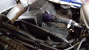
new PCV valve to handle the valve seeing boost, but still regulate how much it can vent.
Not the happiest with the anno finish.. wanted the purple a little lighter..
One of these days I will get the hang of it (the purple dyes insanely fast for some reason)
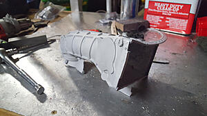
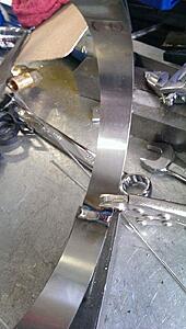
And then there has been this new A2A intercooler inthe works as well..
end tanks had to be machined in several pieces.
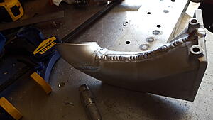
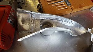
other side pre grinding
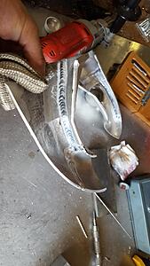
after grinding back surface welds
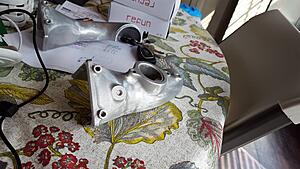
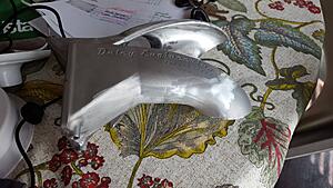
and all together
That's all for now.
A lot more has been going on, but I haven't taken pictures of a lot of it, and there is also a good bit of duplicative wheel spinning going on. (mostly in the electronics and PCB design side (printed circuit board) )
But I just cannot get to where I like everything I have done...
So this has been in the pipeline for a while
new PCV valve to handle the valve seeing boost, but still regulate how much it can vent.

Not the happiest with the anno finish.. wanted the purple a little lighter..
One of these days I will get the hang of it (the purple dyes insanely fast for some reason)


And then there has been this new A2A intercooler inthe works as well..
end tanks had to be machined in several pieces.


other side pre grinding

after grinding back surface welds


and all together


That's all for now.
A lot more has been going on, but I haven't taken pictures of a lot of it, and there is also a good bit of duplicative wheel spinning going on. (mostly in the electronics and PCB design side (printed circuit board) )
#550
11-21-2016, 08:42 PM
been a while! phew!
Been terrible at cataloging stuff.
Anywho. Made a circuit board to distribute power and light signals to the aftermarket gauges. Ran into an issue with using the interior 'running lights' as a source for dimming the gauges.
- more info in this post here :
https://www.northamericanmotoring.co...nd-solved.html
in a nut shell: interior lighting circuits that turn on with the headlights are dimmed via a pulse width modulated signal. The innovate gauges did not like this as their light reference. Had to run a tap to an exterior running light instead. I choose the drivers side front running light commonly tapped for light bars.
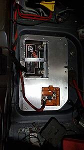
At any rate here is my power distribution board. Don't worry. The mess of wires is mostly from doing all of this testing and troubleshooting. Will be cleaned up and routed nicely before I am finished
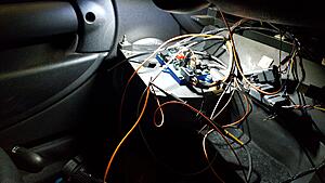
Board allows for up to 5 gauges that need a light signal to plug into it, and has 2 extra sockets that each have power and ground hookups (one of these sends switched power to my boost solenoid)
All outlets are individually fused. Board is a 4 layer design with power and ground planes, and I left lots of large pads all over the board to help with thermal management. She runs cool as a cucumber in my initial tests
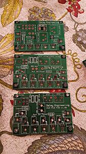
picture of the boards evolution.
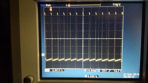
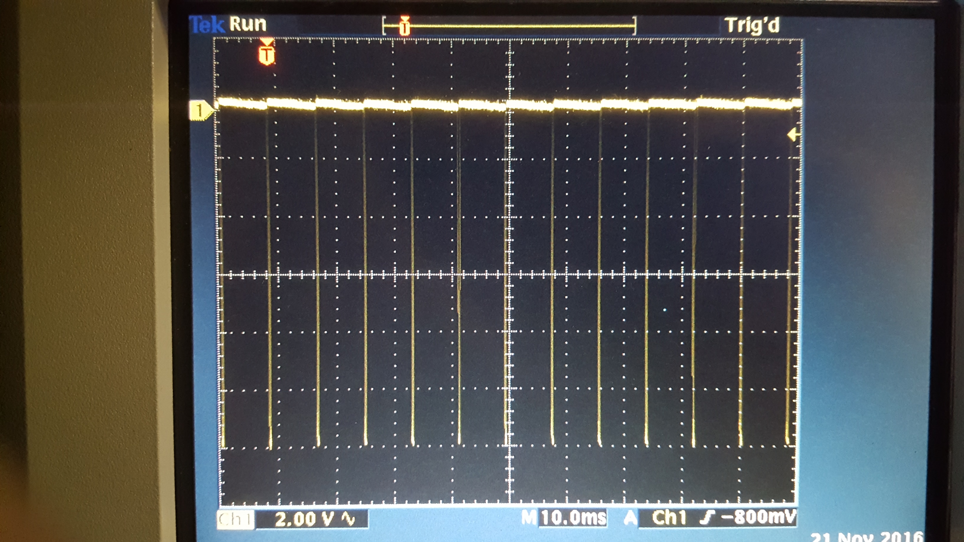
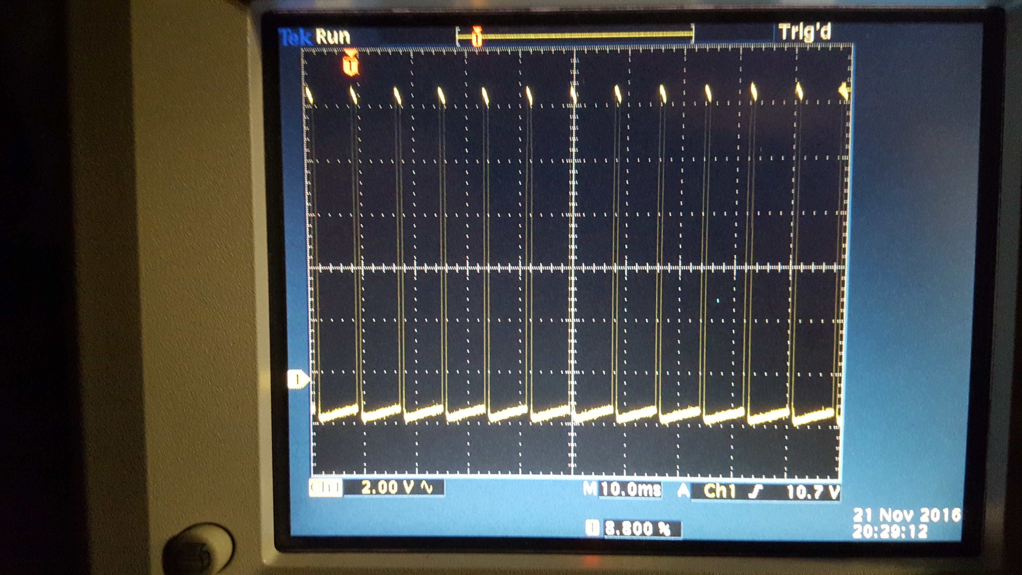
Few shots of the PWM circuit:
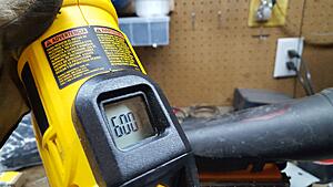
full brightness:

halfish:
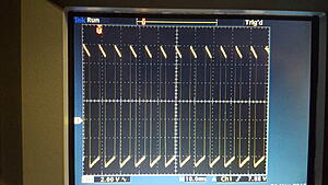
dim:
now onto some shots of other things I have been up to, by no means is this exhaustive. Lots went into the background, or I just didn't want to put into this post.
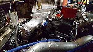
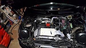
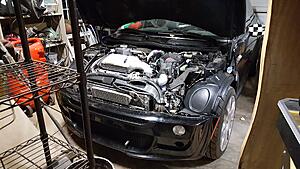
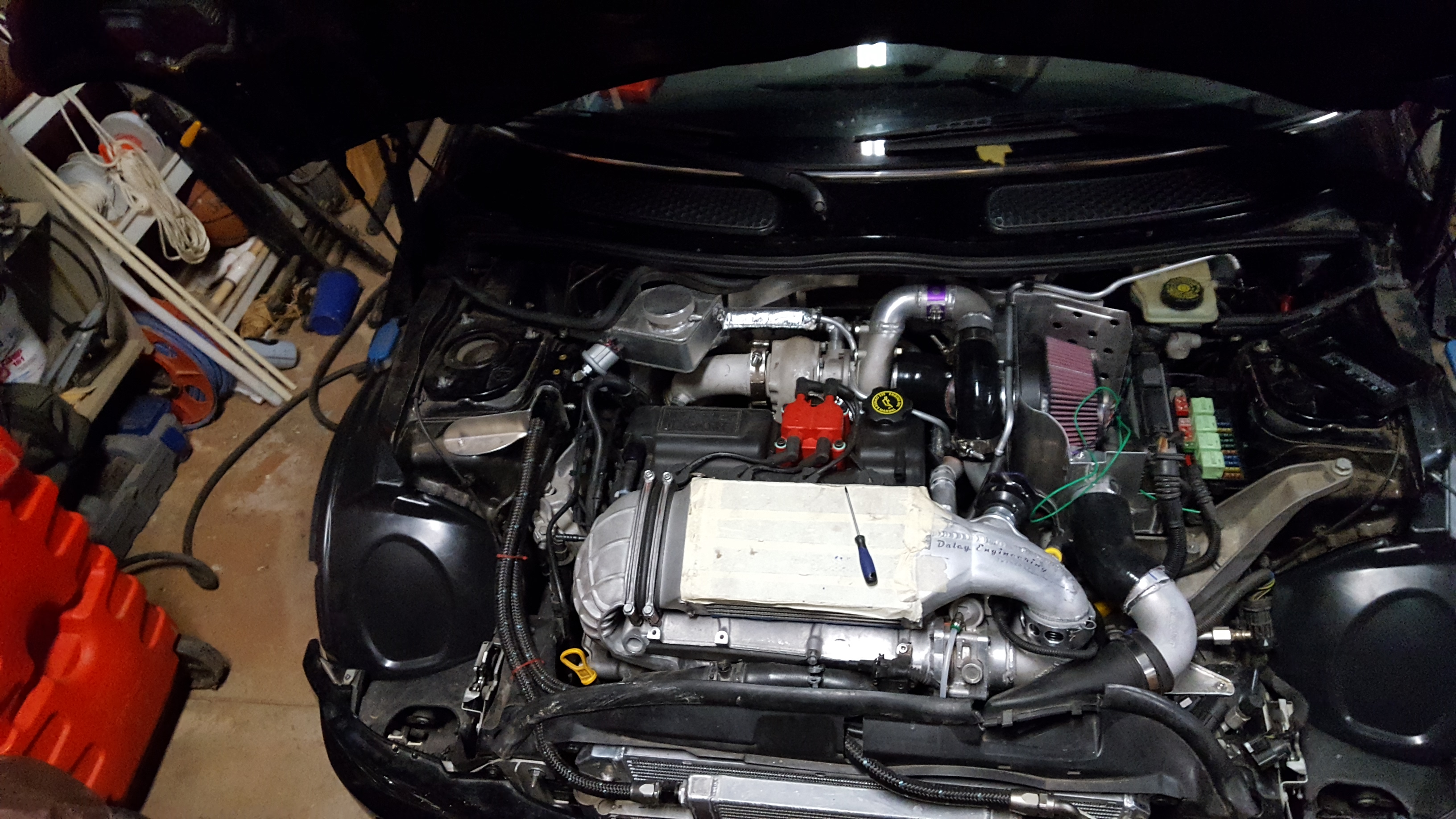
so to start, a engine bay top-shot of current status.
And things that were done:
oh, I also finished the exhaust! (again...)
And wrapped the downpipe! (that I re-did to add clearance and put the O2 sensor in a better spot)
kind of nuts to see the new vs old (l vs r respectively) around the v-band
color coded my reference lines (anodized) to the wategate so as to not mix them up! (a few friends have had... issues in the past. Not my work! just learning from their mistakes )
)
new twincharge bypass.
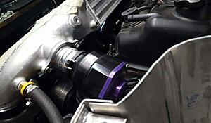
and the one 'expose' in this post will be making the boost control mount and setup.
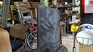
cutting the sheet. (jigsaw and varibit. you can do this too!)
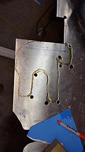
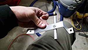
then just bend it up in a vice with a cheap 'press brake' die, and bead roll it! (perhaps I lost you... sorry!) Then mount the solenoid, bend up some tubing, bubble one end, make some mounts, do a little welding, etc.
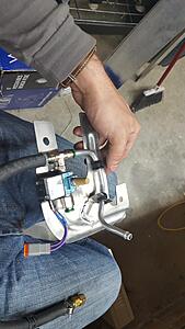
other line bent and attached. The metal bracket between then 'clicks' over the grommets. The 'lone' grommet is for vibration dampening.
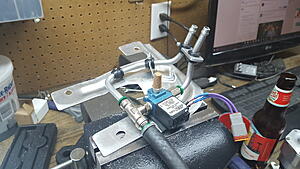
where it mounts (the two right screws were installed with riv-nuts in typical-me fashion.
airbox installs on top (onto the vibration isolation mounts)
-.080 3003 alu sheet, cut and beadrolled by me.
where it's main reference port comes from.
had to form the stock airbox inlet tube.
clearance. Eh. actually not quite. changed onced I bolted the front end all the way up. whoops! (need to form it some more)
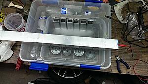
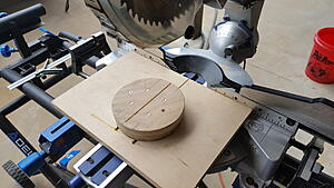
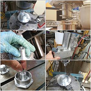
switching gears again, here is a good way to cut mandrel aluminum tubing if you ever need to. cut some wood blocks at the ID of the bends. Enough to get them high enough for midline.
Circles are mounted in some slots to allow adjustment.
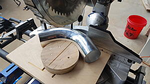
This was for making the new intake tube. I also had to make a new, low-profile 'bellmouth'
Decided to draw it myself. Made a wood mandrel, and pulled it in with a jack screw and some steel plates. My pipe expander end happened to work perfectly for the ID.
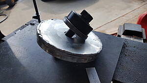
plate I used as a backing.
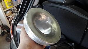
drawn
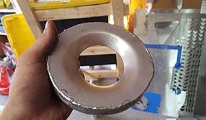
welded and ground back
onto the next thing! the new DV valve (more in detail)
Just some images this time. Too much to talk about in the realm of why and how, just enjoy
that's all for now! almost done...
overview shot
Been terrible at cataloging stuff.
Anywho. Made a circuit board to distribute power and light signals to the aftermarket gauges. Ran into an issue with using the interior 'running lights' as a source for dimming the gauges.
- more info in this post here :
https://www.northamericanmotoring.co...nd-solved.html
in a nut shell: interior lighting circuits that turn on with the headlights are dimmed via a pulse width modulated signal. The innovate gauges did not like this as their light reference. Had to run a tap to an exterior running light instead. I choose the drivers side front running light commonly tapped for light bars.
At any rate here is my power distribution board. Don't worry. The mess of wires is mostly from doing all of this testing and troubleshooting. Will be cleaned up and routed nicely before I am finished

Board allows for up to 5 gauges that need a light signal to plug into it, and has 2 extra sockets that each have power and ground hookups (one of these sends switched power to my boost solenoid)
All outlets are individually fused. Board is a 4 layer design with power and ground planes, and I left lots of large pads all over the board to help with thermal management. She runs cool as a cucumber in my initial tests
picture of the boards evolution.

Few shots of the PWM circuit:
full brightness:
halfish:

dim:
now onto some shots of other things I have been up to, by no means is this exhaustive. Lots went into the background, or I just didn't want to put into this post.
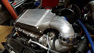
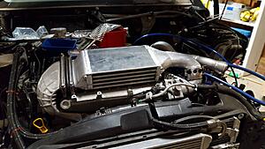
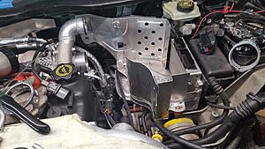
so to start, a engine bay top-shot of current status.
And things that were done:
- Changed the intermediate-boost pipe yet again
- Made an air box!
- mounted the boost solenoid under the air box and above the tranny
- made yet another iteration on my twincharge bypass setup.
- heat formed the factory 'in;et' piece from above the radiator to clear the new intake
- lots of wiring - with protective casing, proper crip terminals, and heatshrink galore!
- many a mess was made
- and much more
oh, I also finished the exhaust! (again...)
And wrapped the downpipe! (that I re-did to add clearance and put the O2 sensor in a better spot)


kind of nuts to see the new vs old (l vs r respectively) around the v-band

color coded my reference lines (anodized) to the wategate so as to not mix them up! (a few friends have had... issues in the past. Not my work! just learning from their mistakes
) 
new twincharge bypass.

and the one 'expose' in this post will be making the boost control mount and setup.
cutting the sheet. (jigsaw and varibit. you can do this too!)

then just bend it up in a vice with a cheap 'press brake' die, and bead roll it! (perhaps I lost you...
sorry!) Then mount the solenoid, bend up some tubing, bubble one end, make some mounts, do a little welding, etc. 
other line bent and attached. The metal bracket between then 'clicks' over the grommets. The 'lone' grommet is for vibration dampening.

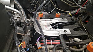
where it mounts (the two right screws were installed with riv-nuts in typical-me fashion.

airbox installs on top (onto the vibration isolation mounts)
-.080 3003 alu sheet, cut and beadrolled by me.

where it's main reference port comes from.

had to form the stock airbox inlet tube.


clearance. Eh. actually not quite. changed onced I bolted the front end all the way up. whoops! (need to form it some more)

switching gears again, here is a good way to cut mandrel aluminum tubing if you ever need to. cut some wood blocks at the ID of the bends. Enough to get them high enough for midline.
Circles are mounted in some slots to allow adjustment.


This was for making the new intake tube. I also had to make a new, low-profile 'bellmouth'
Decided to draw it myself. Made a wood mandrel, and pulled it in with a jack screw and some steel plates. My pipe expander end happened to work perfectly for the ID.

plate I used as a backing.

drawn

welded and ground back

onto the next thing! the new DV valve (more in detail)
Just some images this time. Too much to talk about in the realm of why and how, just enjoy

that's all for now!
almost done...overview shot

Last edited by soccerbummer1104; 11-21-2016 at 08:49 PM.