When you click on links to various merchants on this site and make a purchase, this can result in this site earning a commission. Affiliate programs and affiliations include, but are not limited to, the eBay Partner Network.
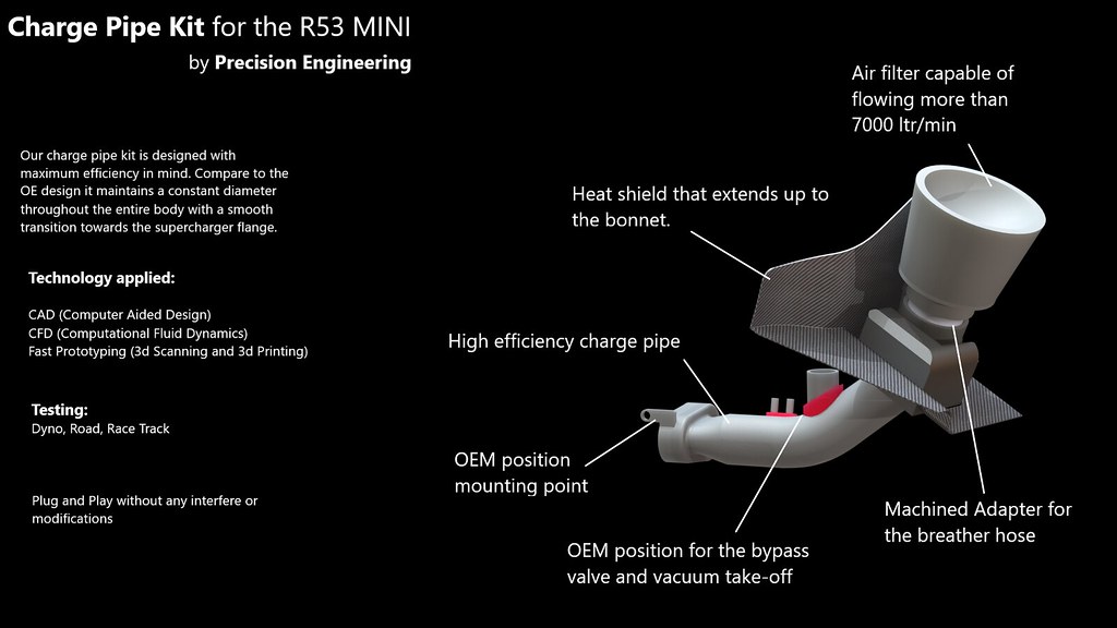
When I started thinking how the OE design could be improved, my priority was the charge pipe. Due to many geometrical changes there are turbulence created in the airflow path. To avoid that a charge pipe was designed that keeps the throttle body diameter (it can be altered for custom ID) through out the body of the charge pipe. Then a smooth transition to the supercharger flange ensures a nice and smooth airflow path to the entrance of the supercharger.
by https://www.flickr.com/photos/141887782@N03/, on Flickr
The OE mounting points remained the same, the opening towards the supercharger inlet has a tight fit, like the OE unit, thus the flange seats perfectly ensuring a perfect sealing. Additionally the bypass and the vacuum take-offs remain in the OE position.
Material:
The material of the charge pipe will be carbon fiber. The reason for going with that material instead of a casted solution is the available space was not enough. That means the charge pipe needs a very thin wall, 2mm , which is extremely hard to be done by the traditional casting methods. Carbon Fiber gave me the mechanical properties I wanted plus the extra thin walls. The only problem was the redesign of the mould, with now having more than 10 parts in total. As a result the initial hypothesis of 3 months of design had jumped to 8 months. At the end of the post, pictures of a pre-prototype charge pipe can be found.
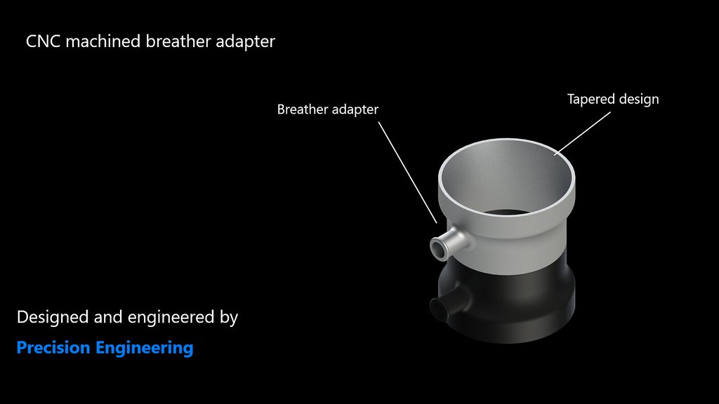
Machined Adapter:
The kit will come with a machined adapter for the air filter in order the PCV system to operate as it was design by the factory. Additionally the PCV adapter ensures that the vehicle operation is environmental friendly and it is not a MOT fail (depending the country). Lastly your aircon will not have any oily smell when you operate it (in some vehicles there is an oily smell if the PCV hose is disconnected.)
by https://www.flickr.com/photos/141887782@N03/, on Flickr
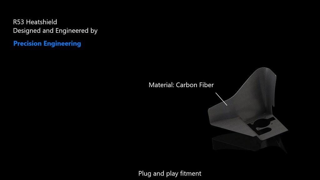
Heat Shield:
The kit comes with a carbon fiber heat shield that ensures no hot air will go to your air filter. The shield is extended up to the bonnet and the way it is designed (see pics) hot air from the radiator will not go to your air filter. I will try to find some more pictures in order to make easier for you to understand how it is.
by https://www.flickr.com/photos/141887782@N03/, on Flickr
Air Filter:
The air filter is capable of more than 7000ltr/min figure which is more than enough a car with the usual mods (17% reduction pulley, 14.5 psi more or less).
So in what stage the charge pipe is now?
As I mentioned above in the prototype stage! That means the CAD, flow and stress simulations are done. Additionally the fitment have been verified by using fast prototyping methods (3d printing and 3d scanning) and the actual first product should be ready in the following months. done? I want to continue to real world testing, dragstrip , racetrack and city driving.
At this point I would like to thank the North American Motoring forum and all the users. Please leave your comments, questions, concerns it will be really helpful for the development process.
PM: I am working on a website and blog, but I think I need at least 1 to 2 months.
Somehow the pictures are double. I tried to change that in the editing section but when I am there everything seems fine! Maybe it is my browser, do you have the same problem?
I am using the bbc code from flickr to share the pictures here.
Keep an eye on the thread, I will try to post all the updates.
Sometimes I upload things on my facebook page so you can check that from time to time for news. https://www.facebook.com/Precision.E...ence.of.speed/
I would be happy to collaborate with someone in order to expand the knowledge and make more testing ! I am anticipating for the next week (end of it) as I might have something more solid....
Looks much better than the stock plastic crap that "Sometimes" seals and other times not lol.
It is tricky indeed.
But interesting part the same time!
I believe it is tricky because of the way the whole assembly connects (plus the limited space). Thus a small mistake could create sealing problems.
Looks much better than the stock plastic crap that "Sometimes" seals and other times not lol.
I fail to see what is so crap about the stock plastic charge pipe fail to seal unless your gasket is shot or misinstalled. Remember, there is mainly vacuum here. This is the intake to the SC.
I fail to see what is so crap about the stock plastic charge pipe fail to seal unless your gasket is shot or misinstalled. Remember, there is mainly vacuum here. This is the intake to the SC.
I happened to be working on the SC today.
I bought a new Chargepipe, seal AND throttle body gasket from BMW and the alignment of the throttle body bolt holes in relation to the bracket that the throttle body bolts go though was off. I made the bolts fit but it resulted in a vacuum leak. I smoke tested the pipe and found it to leak at the throttle body and come to find out the new part was warped. Fantastic.
I purchased ANOTHER Pipe and seals and this one decided to work. So far.
That's my experience with this plastic crap charge pipe.
I hope this prototype fixes the manufacturing inconsistencies of the OEM piece.
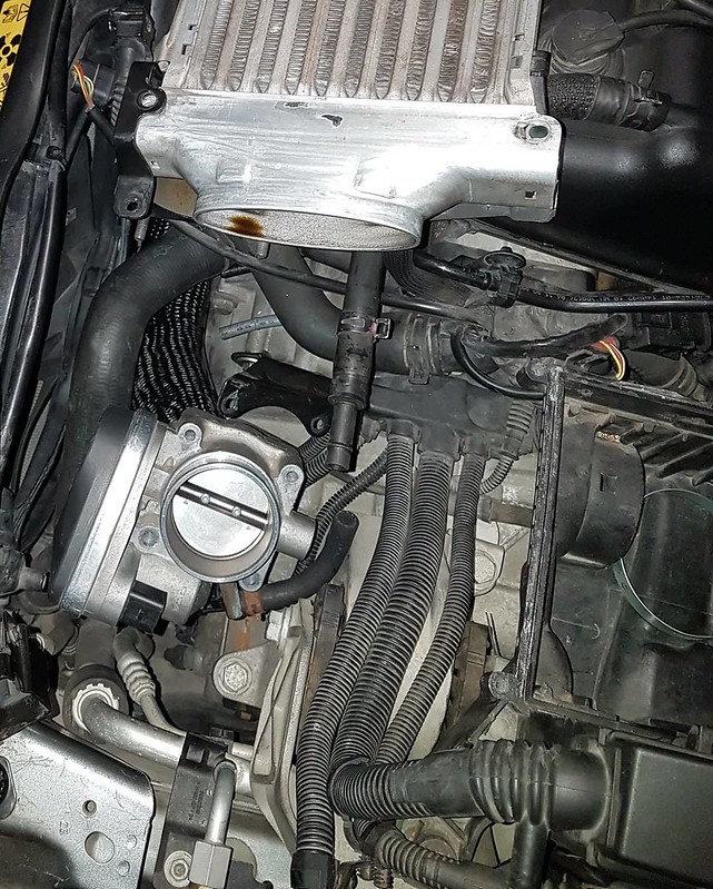
some thoughts why the stock charge pipe is the way it is
To P.E: Please regard this post as a design review in which the presented ask questions.
Until today, I paid little attention to the supercharge air paths and the extreme challenges the engineers faced with packaging the SC into the confined engine bay. Looking at the peculiar shape of the stock plastic charge pipe, and your alternate design, I cannot help but to wonder the reason behind the rather "distorted" appearance of the stock pipe.
At first glance, I immediately assume it is shaped to fit into a space so not to interfere with other stuff that competes with cubic mm. More careful observation tells otherwise, if I have not mistaken. There is almost no reason for the crushed depression on the leading vertical surface as it is not right against anything.
I have two thoughts as to why it is the way it is, rather than making it circular tube like almost end to end:
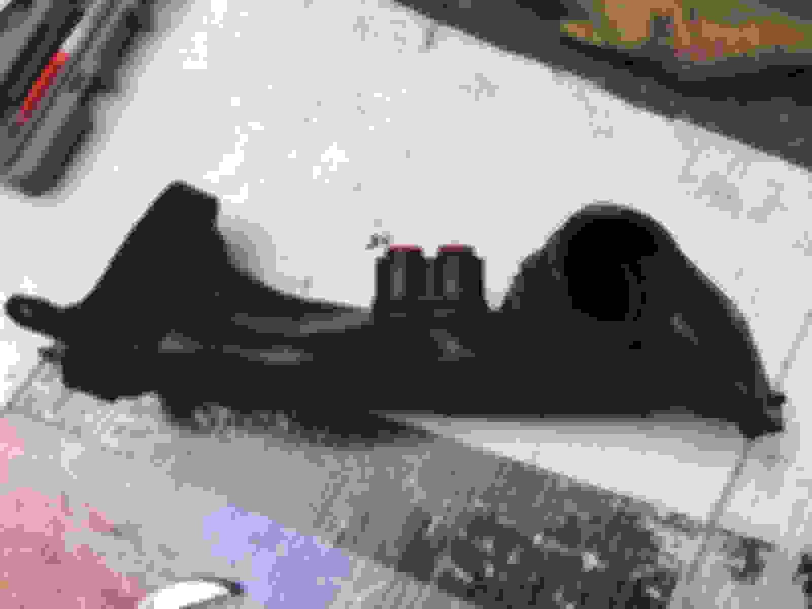
1) The engineers had conducted flow analysis taking into account of the air stream that may consist of quite a bit of spiraling due to the two screw-like rotor scrolls. The result is charge tube that is twisted. Further, as the SC intake port is a flatten oval the charge tube also transitions from circular on the throttle body into a flatten oval when it reaches the SC intake port.
note the flatten and twisted shape of the charge pipe
2) Could the flatten shape of the charge pipe and the dimple is there for acoustic reason - to give the coolant fan back side more space? More space behind the high CFM fan so it won't be so loud and annoying? You don't need to be an engineer if you ever mess with computer cooling fans to know this.
As I scrutinize the stock charge pipe closer, the more I am convince it is done for the reasons in (1) I outlined.
Hello and thank you for your feedback.
As I have seen similar parts in other applications I will say it is for NVH (Noise, vibration, and harshness) reasons. From a performance point of view a design like that will reduce the overall component efficiency. An OE company has to address many problems. The main problem MINI engineers had to solve was how to make that engine scream less (it is a noisy engine). They had to sell the car not only to the enthusiast but to a family guy as well. By making this constant design changes and by knowing the frequency of the engine they manage to cover some of the supercharger noise (in a wide frequency range).
Now about the flatten oval shape:
The prototype changes to that shape, in an earlier stage than the OE component in an attempt to reduce turbulence close to the supercharger inlet. There is not step between the oval shape and the rest of the pipe as you will see in the OE component. You will only see smooth transitions. Why they did that? Because the manufacturing cost will increase. They had to build a whole car with a specific budget not only one component.
I hope I answered your question.
Edit:
Please do not think that I am trying to support that my design will performe X amount more. I know that I do not have data to back it up (dyno, racing track, delta factor). For now I can only answer questions on the design approach. Cross-fingers as this week I will have some big updates !!
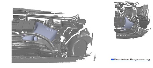
Just in case you wondered how a 3D scanned engine bay looks like ! I though it will be nice to share with you guys.
The picture on the top is the engine scanned file and picture below is the engine bay with the charge pipe kit (3d model).
" target="_blank">
I do not know if you are familiar with 3d scans but that's how you have to prepare the engine bay for the scan !! In order to capture a detailed model it is preferable to have a white mat surface in a low light environment.
I envy your access to this amazing equipment, or have one in your garage?
What is the reason for masking the intercooler, and the holes of the strut mounts? Too much unneeded data, or scatter of beams?
Hello there!
I do not have that equipment so every time I have to rent one ! 3D scan will be my first big buy for the start up, as it is an amazing machine, you need though a very good computer ( for now I am ok ) to deal with a file with millions or triangles (mesh) ! I mask the cooler and the holes i the top mount because of the white dust you see. Although it is easy to remove with a wet cloth, it will be so hard to do so in very small places. Also I do not need the fins of the cooler for example, but I have the overall dimensions of the engine bay. I did a 3d scan in an r56 as well (that's a nice project but I will share it with you guys a bit later, as all my resources are going to the r53 now). As it was not my vehicle I use way less spray, but the final file has more gaps ( or errors if you like).
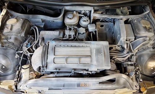
cant see any of the pics everything is blocked but I like the idea, and those red connectors break & hard to get. On bmw's inlets came out a couple years ago, something everyone overlooked for years turned out to be really good gains, 30hp on a bmw n54.
flickr is blocked here on the factory manifold there's red connectors that the vac lines plug into, those things are an issue if they break they are impossible to get.
Anyone else that can't see the pictures ?
Facebook page should be ok.
Ah ok I get you now. No I am not using those red clips. The vacuum lines are made from carbon fiber like the rest of the pipe.
Hello guys I haven't update the thread for a while. I have some excited news ! Tomorrow I will try for first time a fully functional prototype made from carbon fiber.
The last two weeks I have been trying to make a complete closed airbox.
You can see a picture below. What do you think? Which version do you prefer this or the previous?
I think this iteration is better as I assume the airbox is now move in unison with the engine/gearbox. For the previous version which attempt to erect a hot air barrier extending to the bonnet. That design must take into account how engine rocks (by leaving adequate clearance at the top), including worst case movements like hitting a big bump, or god forbid when the motor mount fails.
Are you lowering the throttle body to make more volume for the filter/airbox?
I think this iteration is better as I assume the airbox is now move in unison with the engine/gearbox. For the previous version which attempt to erect a hot air barrier extending to the bonnet. That design must take into account how engine rocks (by leaving adequate clearance at the top), including worst case movements like hitting a big bump, or god when the motor mount fails.
Are you lowering the throttle body to make more volume for the filter/airbox?
Hi there, yes the throttle body has been moved. Right now I am trying to find the best combo filter element (CFM), space, PCV adapter etc. The air box is in the design stage so I am not so worried as I can change the design many times!
I feel like trying both designs in real life conditions so I can see the difference.
 05-17-2018, 11:20 PM